Installation Guide
These are instructions for installing a GNSS Flex module in the SparkPNT FP.
Open the Enclosure
The FP can be opened by removing the six Phillips head screws located on the bottom of the enclosure's antenna cap.
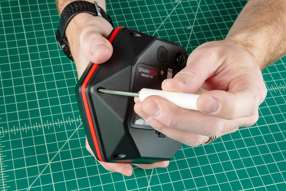
Once unscrewed, the plastic cover should come right off, exposing the ceramic GNSS and WiFi/BLE antennas underneath.
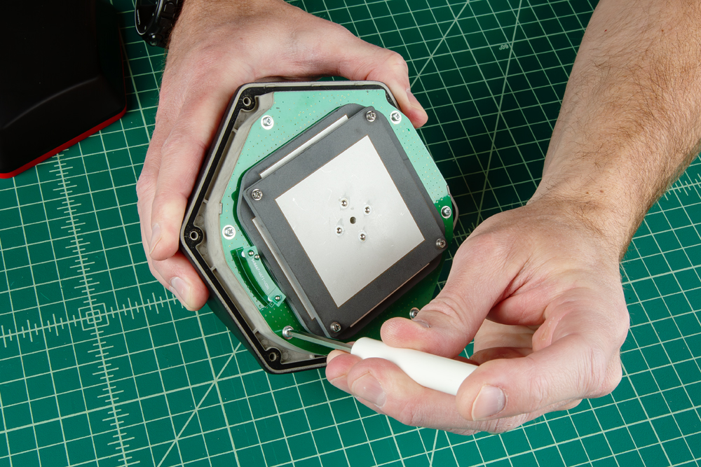
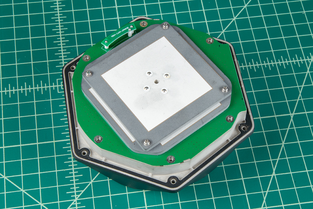
Remove the Antenna Stackup
Once the antenna cover is removed, users can access the six Phillips head screws holding the antenna PCB in place.
With the screws removed, gently and very carefully lift the upper PCB antenna off the enclosure; there are two U.FL cables underneath the antenna. One of the cables is attached to the board underneath; it can be disconnected for better access to the space below.
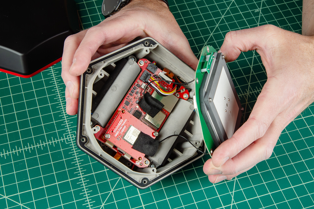
Be careful removing the PCB as one of the U.FL cables is attached to other components.
Install the GNSS Flex Module
Attach the new GNSS Flex module. Be careful to note the alignment of the boards as the header pins are symmetric. The alignment indicator on the GNSS Flex module (circled below), should be pointing away from the display/user interface.
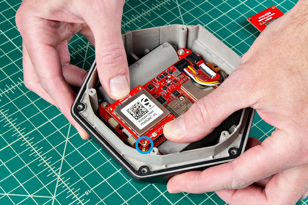
Ensure the position of the alignment indicator on the GNSS Flex module, is pointing away from the display interface.
Once inserted, screws can be added to hold the module in place.
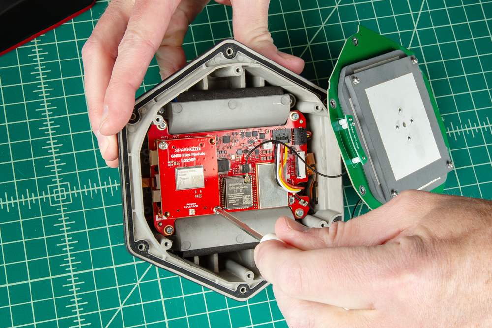
Be careful when threading these screws back in. Over tightening or cross threading the screws into their holes, can strip out the screw head or eventually weaken the material fastening the screw.
Connect the Antenna
Once you have replaced all the necessary components, reconnect the U.FL cables from the antenna element to the mainboard and GNSS Flex module.
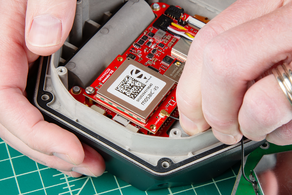
The U.FL cable for the GNSS antenna that comes from the large metal cover of the antenna element, needs to be connected to the GNSS Flex module. Meanwhile, the U.FL cable for the WiFi/BLE antenna that is attached directly to the PCB of the antenna element, should be connected to the mainboard.
The U.FL connectors are held in place with a piece of gaffer's tape. Carefully connect the U.FL cable, users may want to use a U.FL tool to avoid damaging the connection.
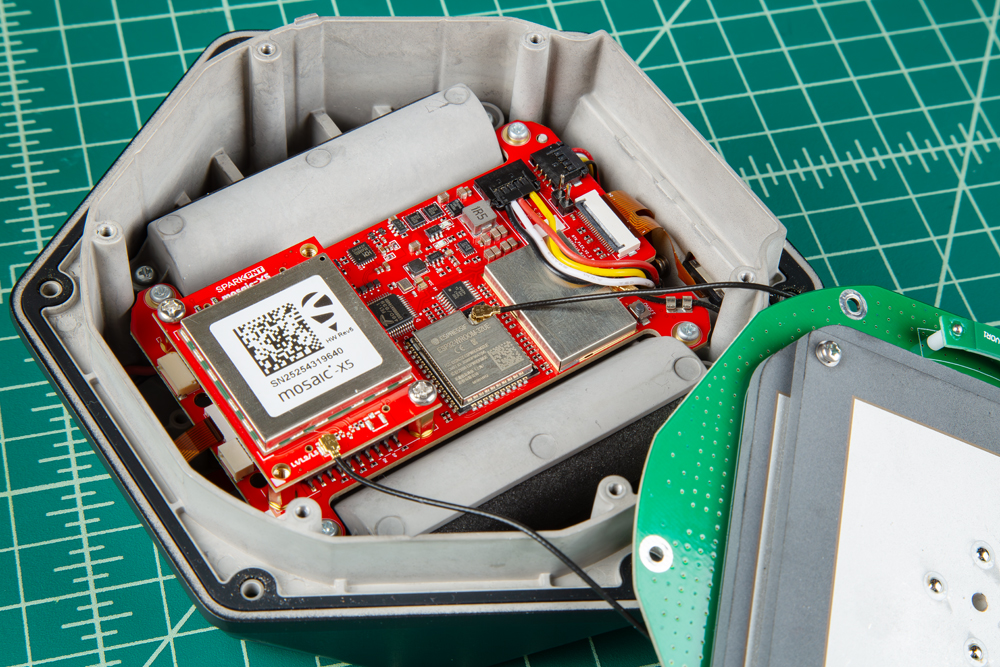
After the cables have been connected, replace the tape that was removed. Another piece can be added to the GNSS Felx module, but is not necessary; this just helps keep the cables in place.
The PCB of the antenna element is cut to align directly with the edges of the enclosure
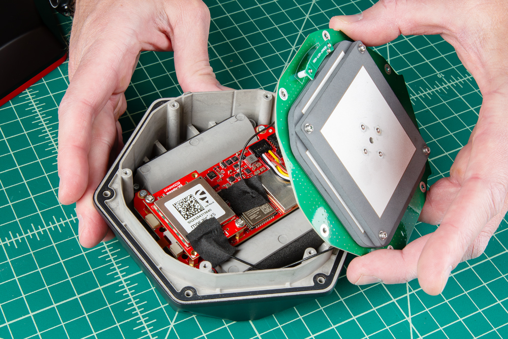
Secure Antenna and Enclosure
All that is left, is to secure the antenna and the enclosure cover with the screws that were removed earlier.
- Don't forget to attach the silicone bumper with the enclosure's cover.
- Be careful when threading these screws back into the cover. Over tightening or cross threading the screws into their holes, can strip out the screw head or eventually weaken the material fastening the screw.
Product Manuals
With your GNSS Flex module installed, please proceed to the associated product manual
SparkPNT FPL
Product manual for the installed LG290P GNSS Flex module
SparkPNT FPL-T
Product manual for the installed LG290P & IM19 GNSS Flex module
SparkPNT FPM
Product manual for the installed mosaic-X5 GNSS Flex module
SparkPNT FPM-T
Product manual for the installed mosaic-X5 & IM19 GNSS Flex module
SparkPNT FPX
Product manual for the installed ZED-X20P GNSS Flex module
SparkPNT FPX-T
Product manual for the installed ZED-X20P & IM19 GNSS Flex module