Quickstart Guide
The SparkPNT FP is a cost-effective, rugged, MFi certified, GNSS RTK surveying unit with a built-in RF transceiver. Unlike other surveying devices, users can install the GNSS receiver of their choice. Later, it can be easily upgraded when GNSS technology improves, for additional capabilities, or just to match the rest of your fleet. The IP67 rated enclosure is constructed with an anodized die-cast magnesium body and a fracture resistant fiberglass dome. This entire kit ships in a hard-sided case to protect your investment. We've even included extra silicon bumpers to facilitate unit identification and repair.
This unit does not come with a GNSS receiver. A GNSS Flex module can be purchased separately.
Parts List
The SparkPNT FP comes shipped inside a hard-sided carrying case with all the accessories need for users to get right to work. Below, is an overview of all the included parts:
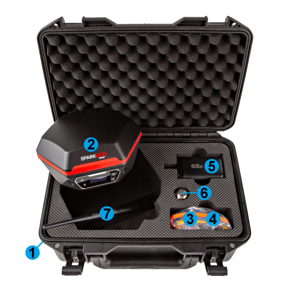
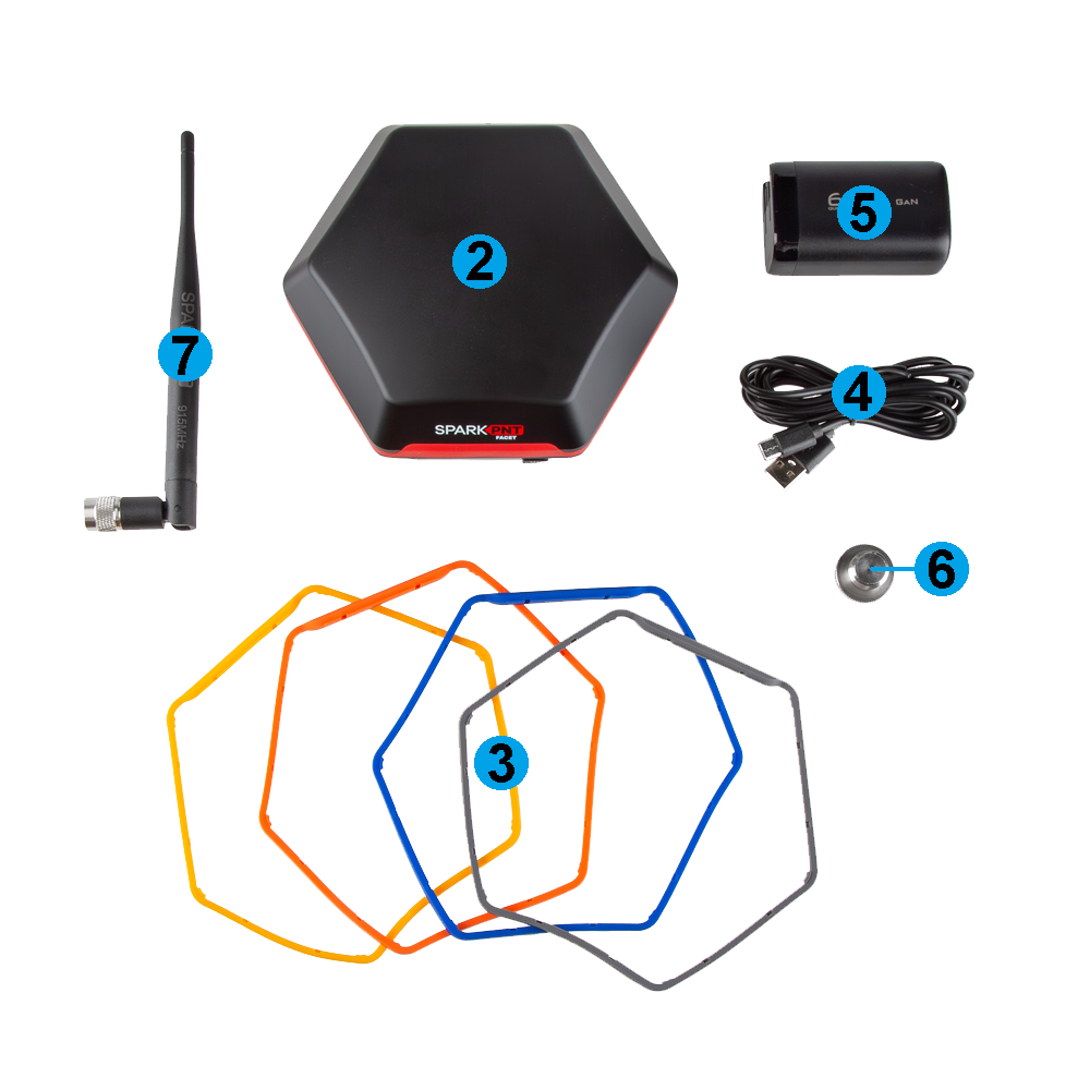
- Carrying Case
- SparkPNT FP
- Silicone bumper set
- USB-C Cable
- USB-C Charger (65W)
- Thread Adapter (1/4" to 5/8")
- LoRa Antenna (915MHz, 2dBi)
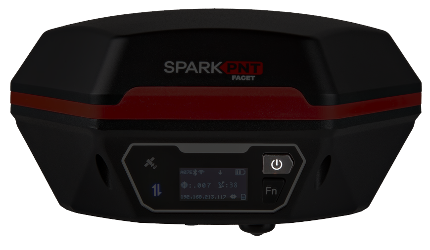
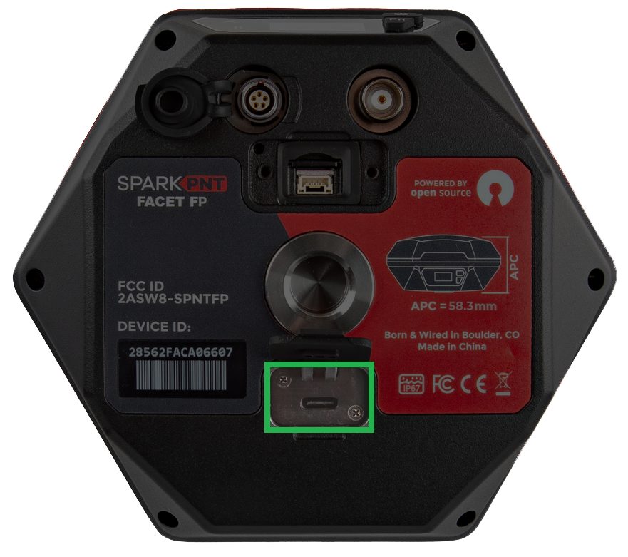
Device Overview
Power
To power on the device, hold the () power button for a few seconds: the device will illuminate the display and beep once. To power down the device, hold the () power button for a few seconds: the device will show 'Shutting Down...' and beep three times.
Battery
-
Battery Charging - The FP supports standard USB charging and can be charged from nearly any device that has a USB port. A red LED on the front display will turn on during charging and turn off when complete. A fully dead battery will charge in about 24 hours.
-
Battery Capacity - The FP includes a 7.2V 6.8Ahr (48.96Whr) battery. This should allow the device to run continuously for more than 50 hours, in worst-case conditions.
Status Indicators
There are three LED status indicators on the front of the FP.

- The GNSS icon () indicates the GNSS pulse-per-second.
- The green LED will blink once per second when a GNSS fix is achieved.
- The Connection icon () indicates the Bluetooth connection status.
- The blue LED blinks once per second while waiting for a connection.
- The blue LED will turn solid once a Bluetooth connection is made.
- The Battery charge LED is located below the power button.
- The red LED will illuminate when attached to a charger.
- The LED will turn off when charging is complete.
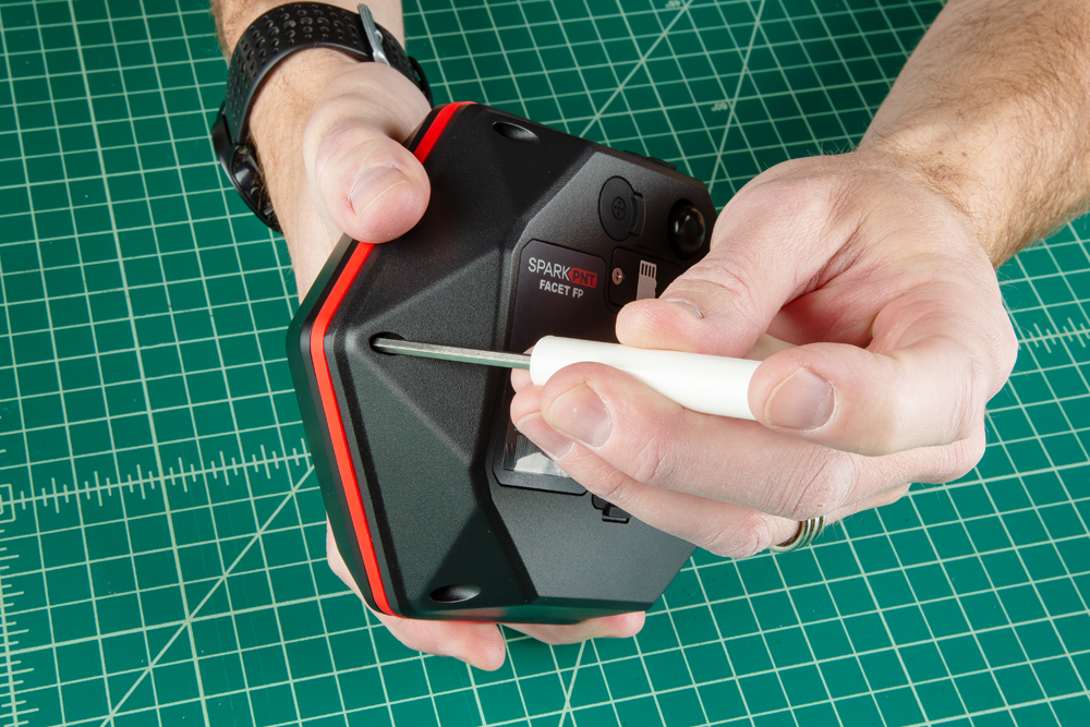
Installation Steps
Open the Enclosure
Remove the six Phillips head screws located on the bottom of the FP's antenna cap.
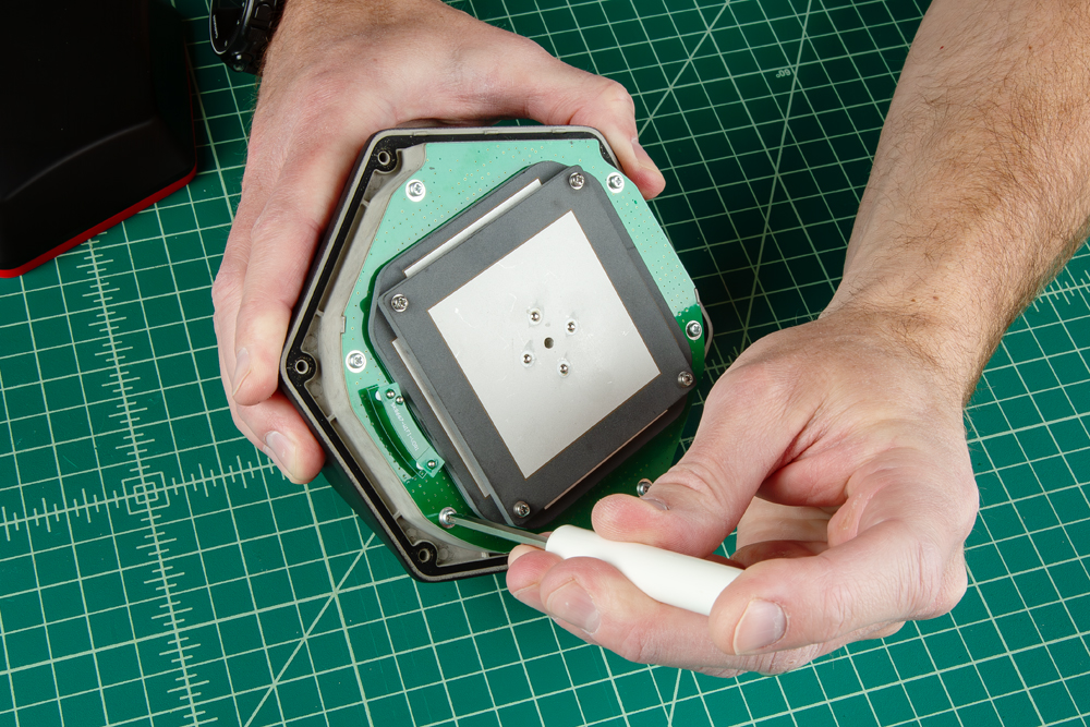
Remove Antenna
Remove the six Phillips head screws holding the antenna PCB in place. Then, gently and very carefully lift the upper PCB antenna off the enclosure; there are two U.FL cables underneath the antenna. One of the cables is attached to the board underneath.
Install GNSS Flex Module
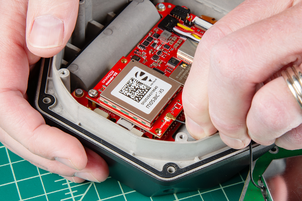
Install the GNSS Flex module. Be careful to note the alignment of the boards as the header pins are symmetric. The alignment indicator on the GNSS Flex module (circled below), should be pointing away from the display/user interface. Once inserted, screws can be added to hold the module in place.
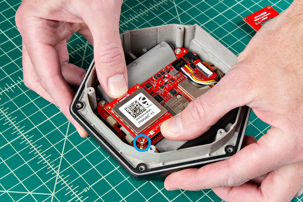
- Ensure the position of the alignment indicator on the GNSS Flex module, is pointing away from the display interface.
Reattach Antenna and Cover
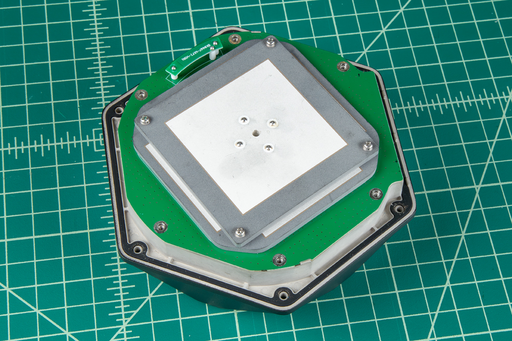
Once installed, connect the U.FL cables from the antenna element to the mainboard and GNSS Flex module.
- The U.FL cable for the GNSS antenna will lead directly to the large metal cover of the antenna element.
- The U.FL cable for the WiFi/BLE antenna will lead directly to the PCB of the antenna element.
All that is left, is to secure the antenna and cover with the screws that were removed earlier. Make sure that the PCB of the antenna element align directly with the edges of the enclosure.
- Don't forget to attach the silicone bumper with the enclosure's cover.
- Be careful when threading these screws back into the cover. Over tightening or cross threading the screws into their holes, can strip out the screw head or eventually weaken the material fastening the screw.
Product Manuals
With your GNSS Flex module installed, please proceed to the associated product manual
SparkPNT FPL
Product manual for the installed LG290P GNSS Flex module
SparkPNT FPL-T
Product manual for the installed LG290P & IM19 GNSS Flex module
SparkPNT FPM
Product manual for the installed mosaic-X5 GNSS Flex module
SparkPNT FPM-T
Product manual for the installed mosaic-X5 & IM19 GNSS Flex module
SparkPNT FPX
Product manual for the installed ZED-X20P GNSS Flex module
SparkPNT FPX-T
Product manual for the installed ZED-X20P & IM19 GNSS Flex module