Equipment Overview
The SparkPNT FPL-T is a cost-effective, rugged, MFi certified, all-band GNSS RTK surveying unit. Unlike other high-precision RTK surveying devices, the GNSS receiver inside of SparkPNT FPL-T can be easily upgraded to meet your performance requirements, match the capabilities of your fleet, or when GNSS technology improves. The FPL-T provides Bluetooth and WiFi connectivity to any mobile device, including Apple iOS devices with its MFi certification. We have also included a built-in 1W 915MHz LoRa radio, to transmit/receive RTK corrections directly with other units that are over 16km (>10mi) away.
We have designed the FPL-T to optimize your on-site workflow:
- When it comes to fleet management, configuring another device is as simple as swapping out the SD card; gone are the days of needing to copy/paste credentials and settings.
- To start surveying positions, simply pair with the FPL-T on any smartphone or tablet, open your preferred GIS app, and access their NTRIP corrections service using the internet/cellular connection of your mobile device.
- The SparkPNT FPL-T can also operate as a base station, to broadcast RTK corrections and function as an NTRIP caster/server.
- When working on a tight deadline, users can also implement our
Base Assistfunction to automatically configure the base station's position in minutes. Great for scenarios, where only precise measurements are required and not the accuracy of their global position; such as surveying the layout of a building. - Using its WiFi capabilities, users can configure the FPL-T to operate as an NTRIP caster/server on a local WiFi network, be used as an access point, or even connect to another SparkPNT device directly using the WiFi 2.4GHz transceiver, great for regions where the 915MHz radio can't be utilized.
- When working on a tight deadline, users can also implement our
The FPL-T also has Galileo HAS corrections enabled by default, users can even operate in remote locations with limited access to data, internet, or cellular services. While it takes a few minutes for FPL-T the PPP algorithm to converge on a solution, the corrections are provided for free from the Galileo GNSS constellation and has global coverage; with <20cm (<8") of precision.
This is all housed in an IP67 rated enclosure and constructed with an anodized aluminum body and a reinforced plastic cover. Our entire kit ships in a hard-sided case, including additional accessories, and a appreciation sticker. We have even included extra silicon bumpers to facilitate unit identification or serve as replacements.
Parts List
The SparkPNT FPL-T comes shipped inside a hard-sided carrying case with all the accessories need for users to get right to work. Below, is an overview of all the included parts:
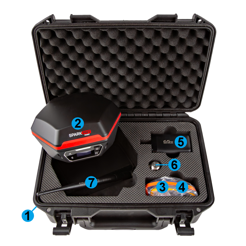
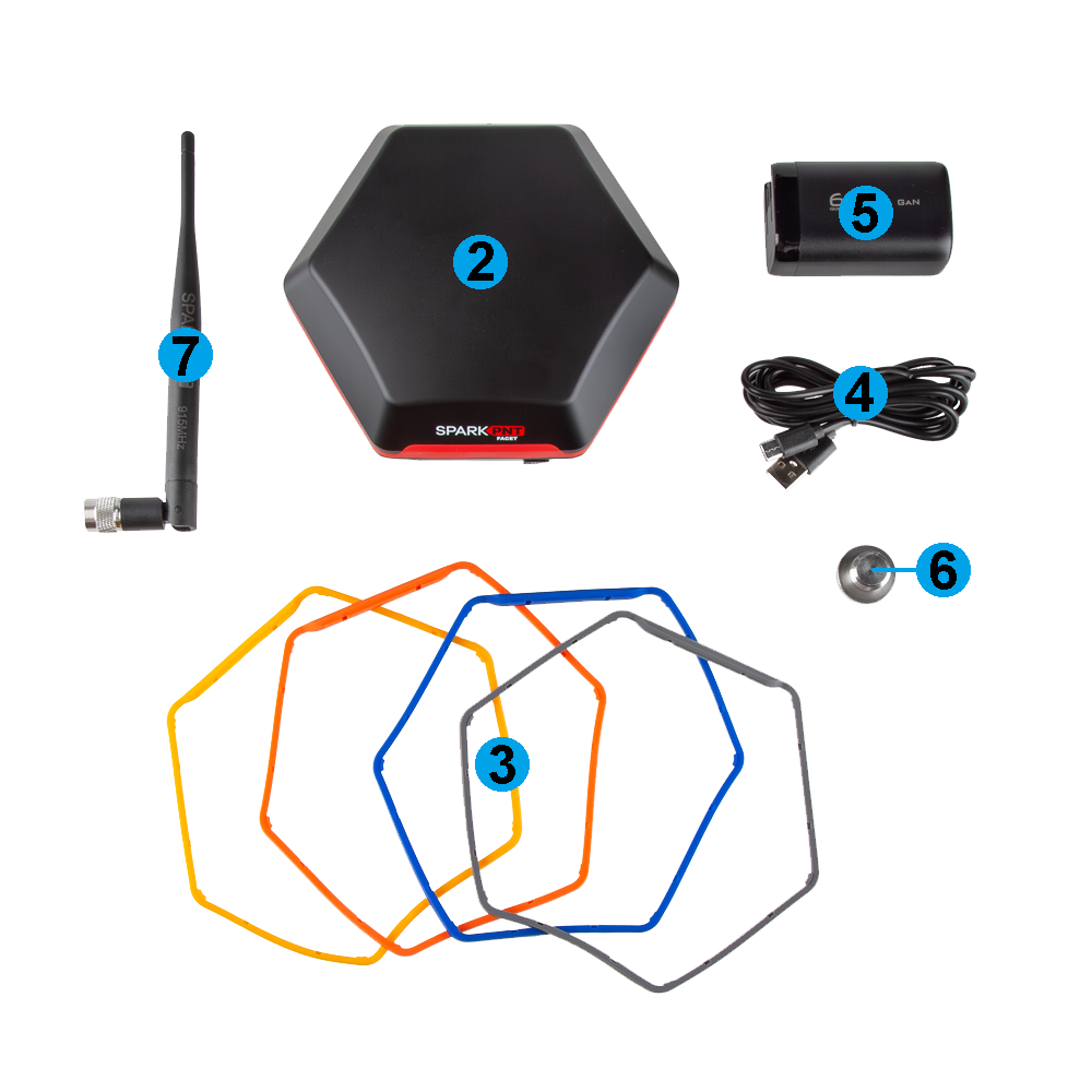
- Carrying Case
- SparkPNT FPL-T
- Silicone bumper set
- USB-C Cable
- USB-C Charger (65W)
- Thread Adapter (1/4" to 5/8")
- LoRa Antenna (915MHz, 2dBi)
Carrying Case
The FPL-T comes with a hard-sided case that includes two holes for pad locks (with shackles up to 6mm in diameter).
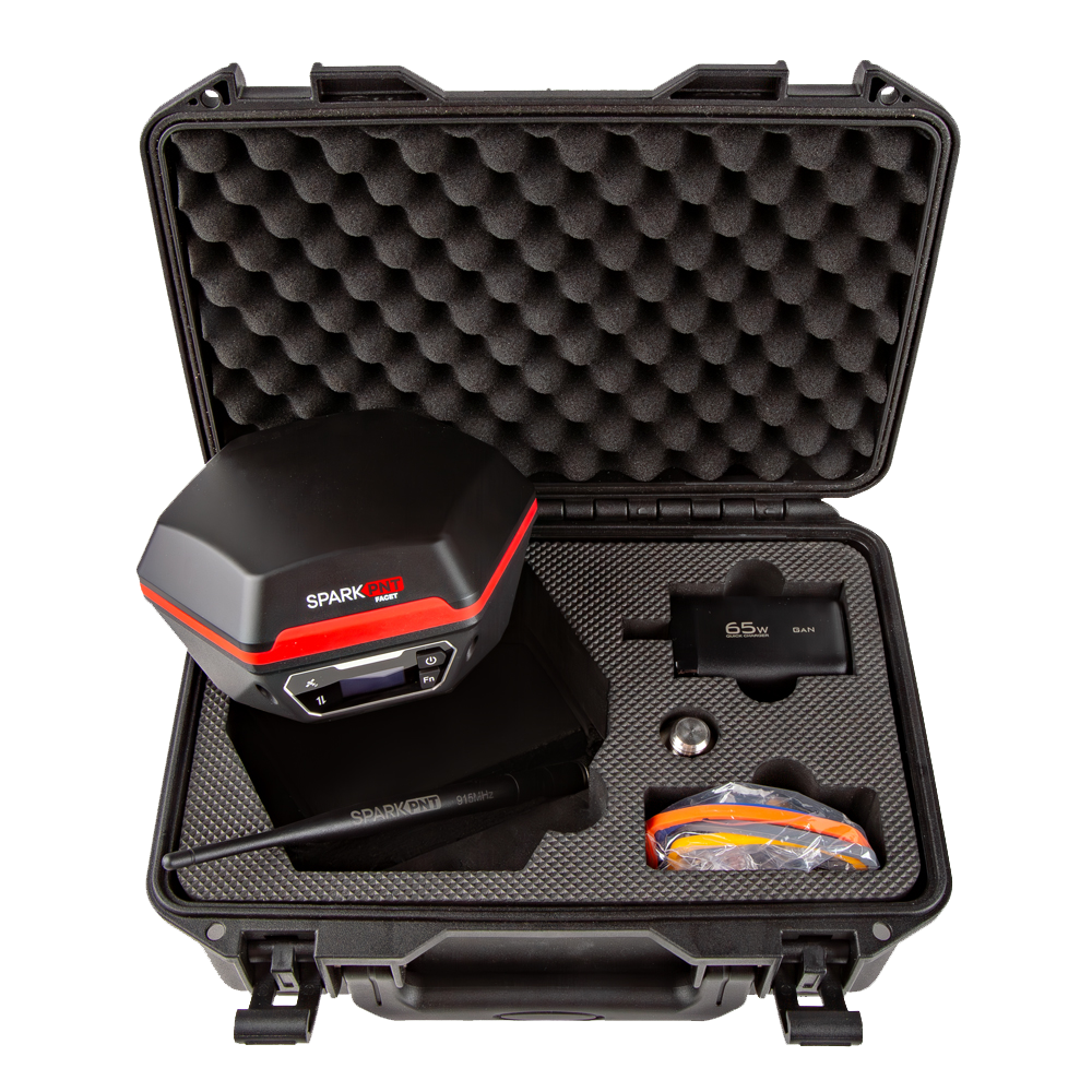
We recommend limiting the shackle diameter to less than 6mm; a 1/4" (6.35mm) shackle will not fit without modifying the case.
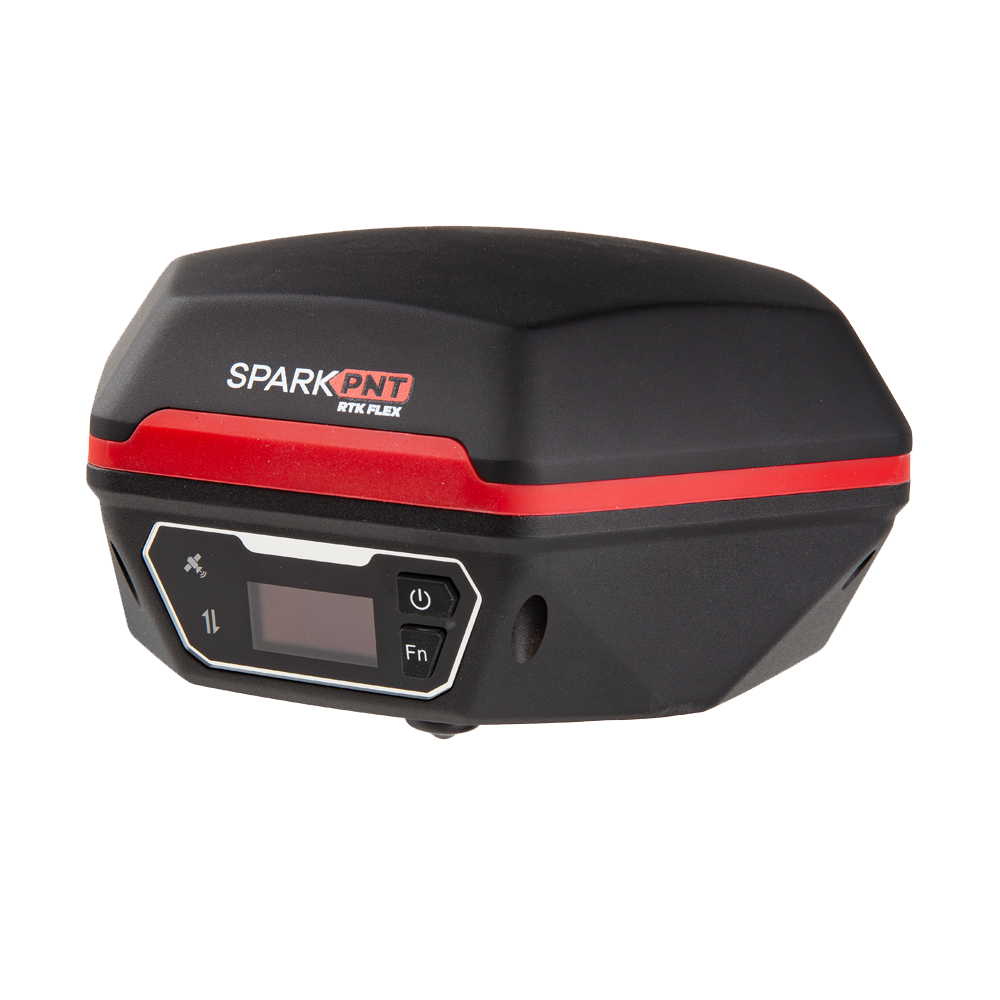
Product Overview
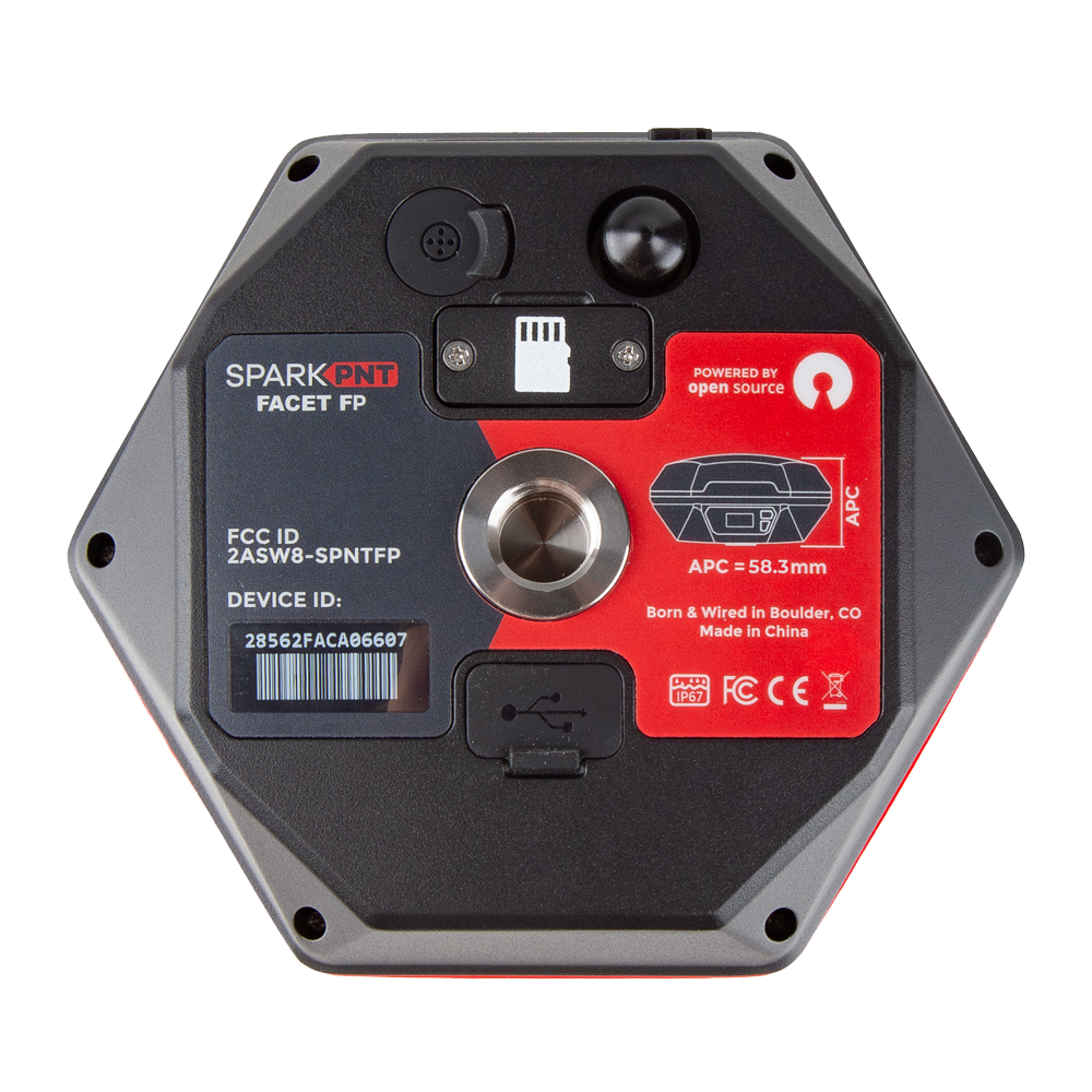
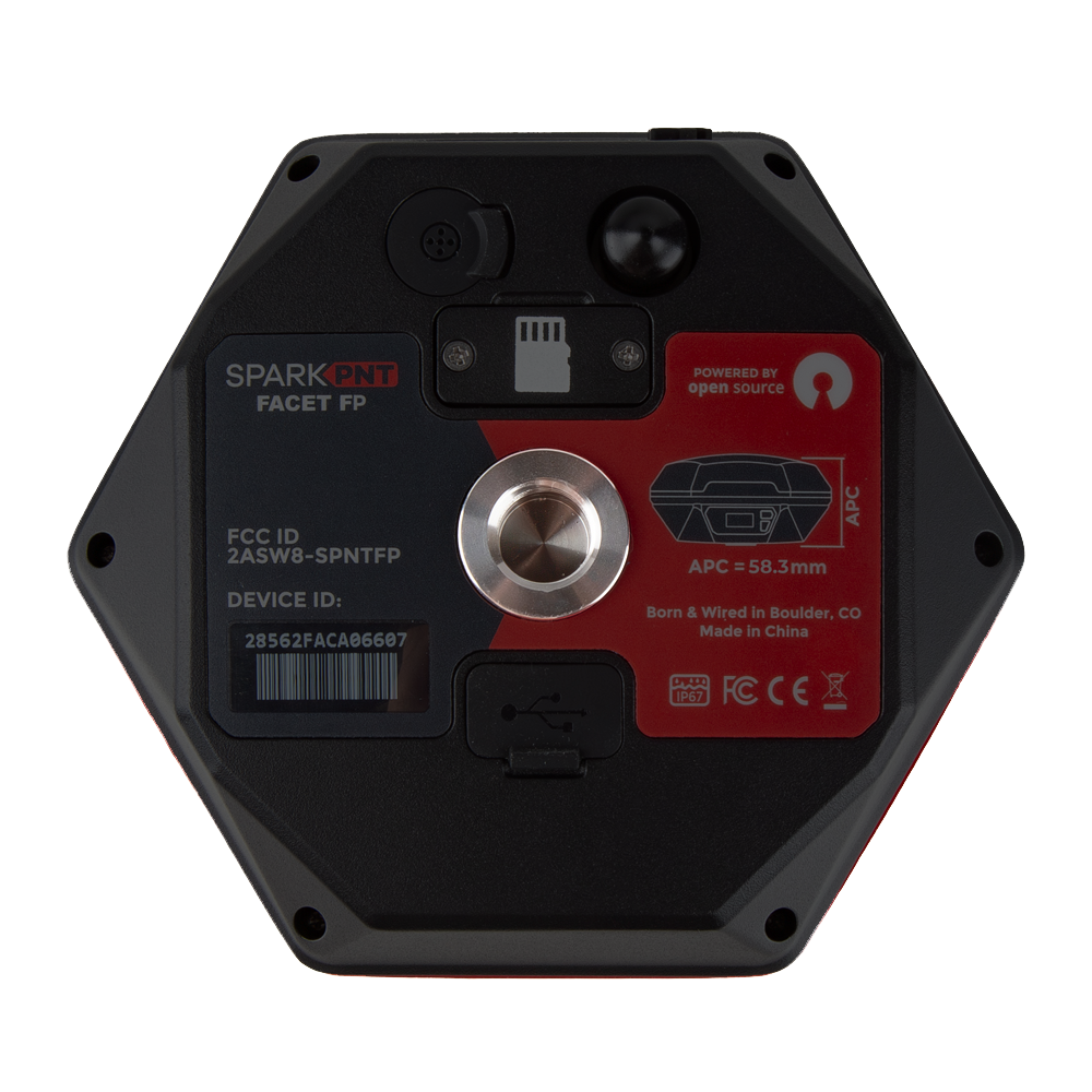
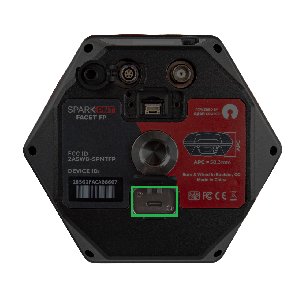
The FPL-T features a rugged aluminum and plastic enclosure, calibrated ceramic GNSS antenna, high-capacity battery, 5/8" threaded base, a basic user interface, and weather-protected data interfaces. The user interface has an OLED display, two user buttons, and two status LEDs. Users can find the data interfaces located on the bottom of the device; including the SD card slot, JST-GH connector, USB-C connector, 5-pin data port connector, and SMA connector. The enclosure is IP67 waterproof, but only if the data interfaces on the bottom are covered.
Enclosure
The FPL-T features a rugged enclosure made of a cast aluminum body with a plastic cover around its embedded ceramic antenna. The enclosure is IP67 rated and is waterproof to 1 meter, for up to 30 minutes, when the data interfaces on the bottom are covered.
The device should not be considered as IP67 waterproof, if the LoRa antenna is attached or any of the ports on the bottom are exposed. The rubber covers need to be fully seated, cover for the JST/SD card slot attached, and the SMA connector capped for the enclosure to qualify for the IP67 ingress protection rating.
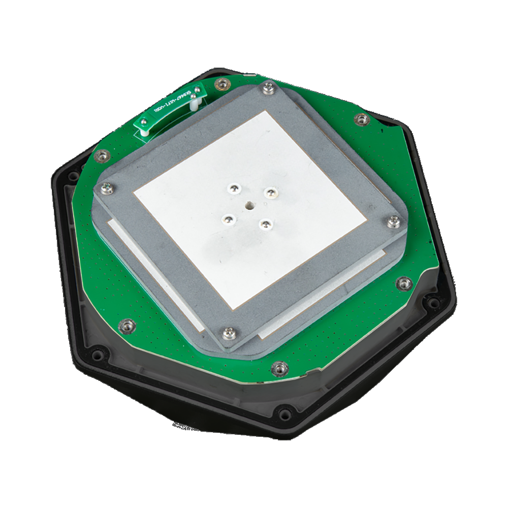
GNSS Antenna
Underneath its plastic cap, the FPL-T features a specially tuned multi-frequency (L1/L2/L5) GNSS antenna and 2.4GHz BLE/WiFi extension antenna.
Don't forget that GNSS signals are fairly weak and can't penetrate buildings or dense vegetation. The GNSS antenna should have an unobstructed view of the sky.
Antenna and North Reference Points
The mounting point at the bottom of the device, where the threaded insert is located serves as the device's ARP (antenna reference point). Additionally, the user interface (front of the device) serves as the device's NRP (north reference point). The distance between the ARP on the FPL-T to the L1 APC (antenna phase center) is 131.7mm and 126.2mm to the L2/L5 APC; with an average of 128.95mm.

Mount Point
The bottom of the FPL-T features a standard 5/8"-11 TPI threaded insert. This is commonly found on surveying equipment and is compatible with most surveying poles. The FPL-T kit also includes a 1/4" to 5/8" thread adapter for additional mounting options.
The center of the threaded insert, on the plane of the device's base, serves at the ARP (antenna reference point) for the device.
Power
To power on the device, hold the () power button for around 3 seconds: the device will illuminate the display and beep. To power down the device, hold the () power button for around 3 seconds: the device will show 'Shutting Down...' and beep three times.
Battery and Charging
-
Battery Charging - The FPL-T features a 49Whr battery and supports standard USB charging. A fully dead battery will charge in about 24 hours.
tipDon't forget to fully close the rubber cover. The enclosure's IP67 ingress rating (waterproof to 1 meter, for up to 30 minutes), is only valid when the all the covers are sealed.
-
Battery Capacity - The FPL-T includes a 7.2V 6.8Ahr (48.96Whr) battery. This should allow the device to run continuously for more than 50 hours, in worst-case conditions.
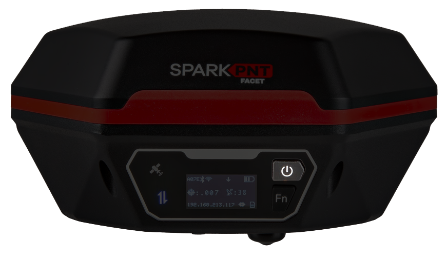
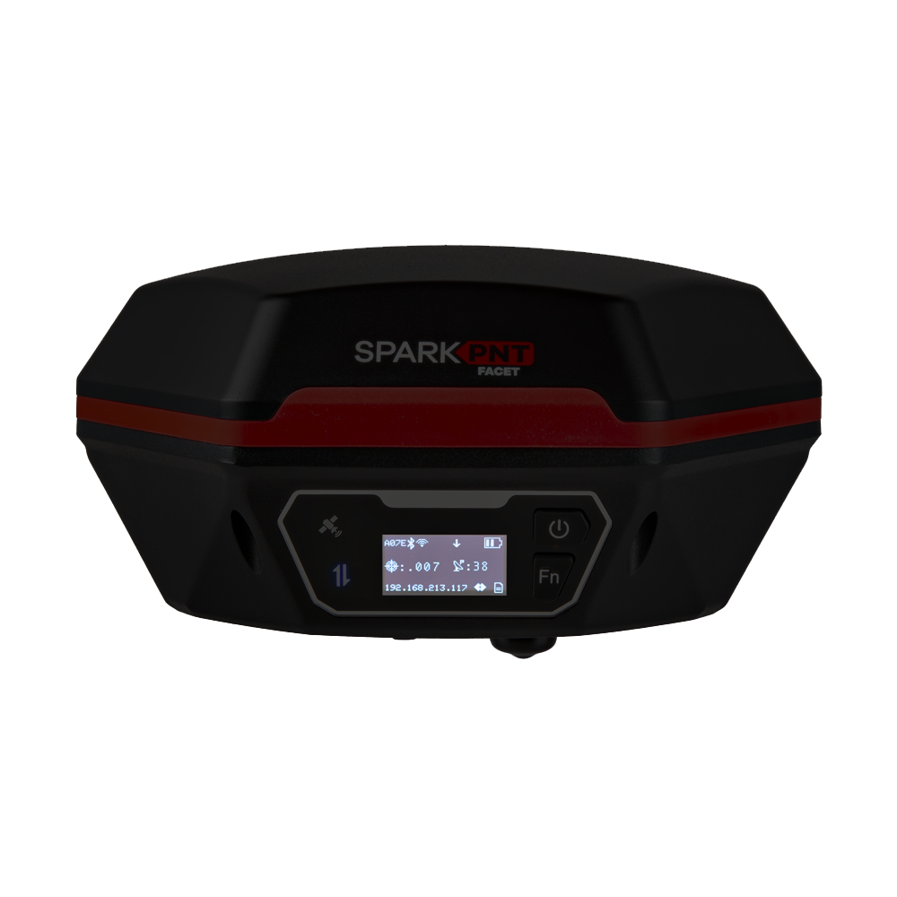
OLED Display
The user interface features an OLED display, two status LED indicators, and two user buttons. The OLED display is used to navigate the configuration menu and display a main screen with the status of the FPL-T.
The center of the user interface also serves at the NRP (north reference point) for the device.
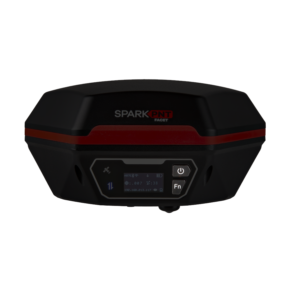
Buttons
There are two user buttons that can be used to turn the FPL-T on /off or navigate the menus displayed on the OLED screen.
- Power the device on or off:
- Hold the () power button down for more than 3 seconds. When the device powers on, it will beep once; whereas, the device will beep three times when it powers down.
- Navigate menu:
- Open menu: From the main screen, press the (Fn) function button once to open the navigation menu.
- Move down/select next option: Press the (Fn) function button navigate down to the next option on the menu of the OLED display.
- Select option/navigate into the sub-menu: Press the () power button to select an option or navigate into its sub-menu.
Indicators
The FPL-T also features two LED status indicators and an internal buzzer for audio feedback to the user.
Status LEDS
There are two LED status indicators on the front of the FPL-T.
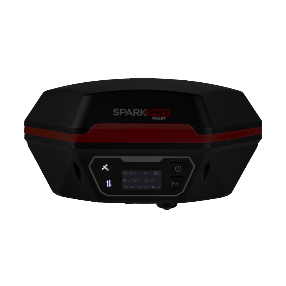
- The GNSS icon () indicates the GNSS solution status.
- A yellow LED will blink once per second when a GNSS fix is achieved.
- A green LED will illuminate solid when RTK Fix is achieved.
- The Connection icon () indicates the WiFi or BLE connection status.
- The LED blinks once per second while waiting for a connection.
- The LED will turn solid, once it is connected to a phone, laptop, WiFi network, etc.
Buzzer
The FPL-T also includes an internal buzzer that provides audio feedback for the user. The following prompts are provided:
- Power On: Beep once
- Power Off: Beep three times
- Awaiting a Connection: Beep twice
Data/Communication Connections
There are five data and communication connections on the bottom of the FPL-T; SD card slot and JST, Lemo, USB-C, and SMA connectors. The SD card slot and JST connector are both enclosed under the same cover.
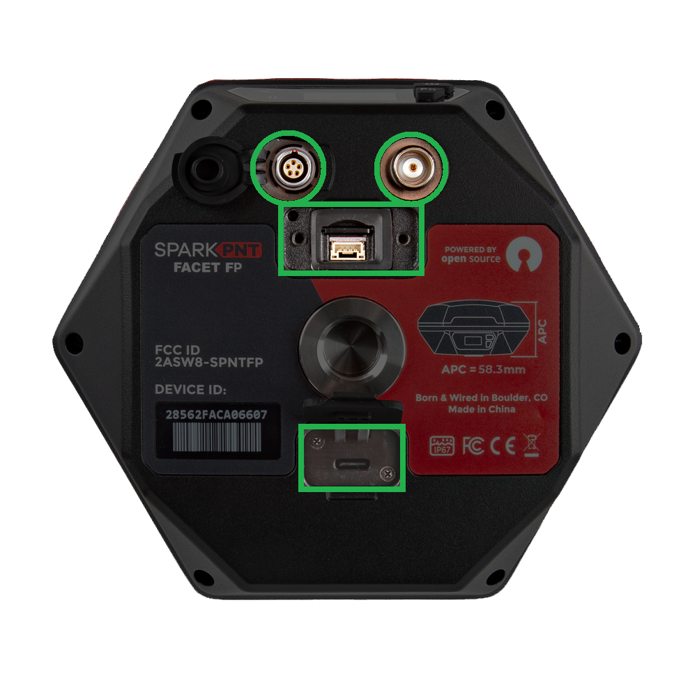
The device should not be considered as IP67 waterproof, if the LoRa antenna is attached or any of the ports on the bottom are exposed. The rubber covers need to be fully seated, cover for the JST/SD card slot attached, and the SMA connector capped for the enclosure to qualify for the IP67 ingress protection rating.
SD Card
The SD card slot and JST-SH connector are covered under the same access port. To access these interfaces, unscrew and remove the cover piece. Users can insert a µSD card that is formatted with FAT32, with a capacity up to 32GB. The SD card can be used to transfer user profiles between devices, log data points, store diagnostic reports.
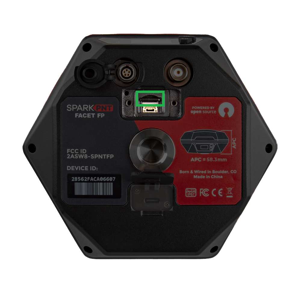
JST Connector
The SD card slot and JST-SH connector are covered under the same access port. To access these interfaces, unscrew and remove the cover piece. The

Lemo Connector
The 5-pin Lemo-style connector is provided to connect the SparkPNT FPL-T with industrial equipment. It breaks out the UART interface of the SparkPNT FPL-T and is compatible with our interface cable and B - Indoor keyed Lemo connectors.
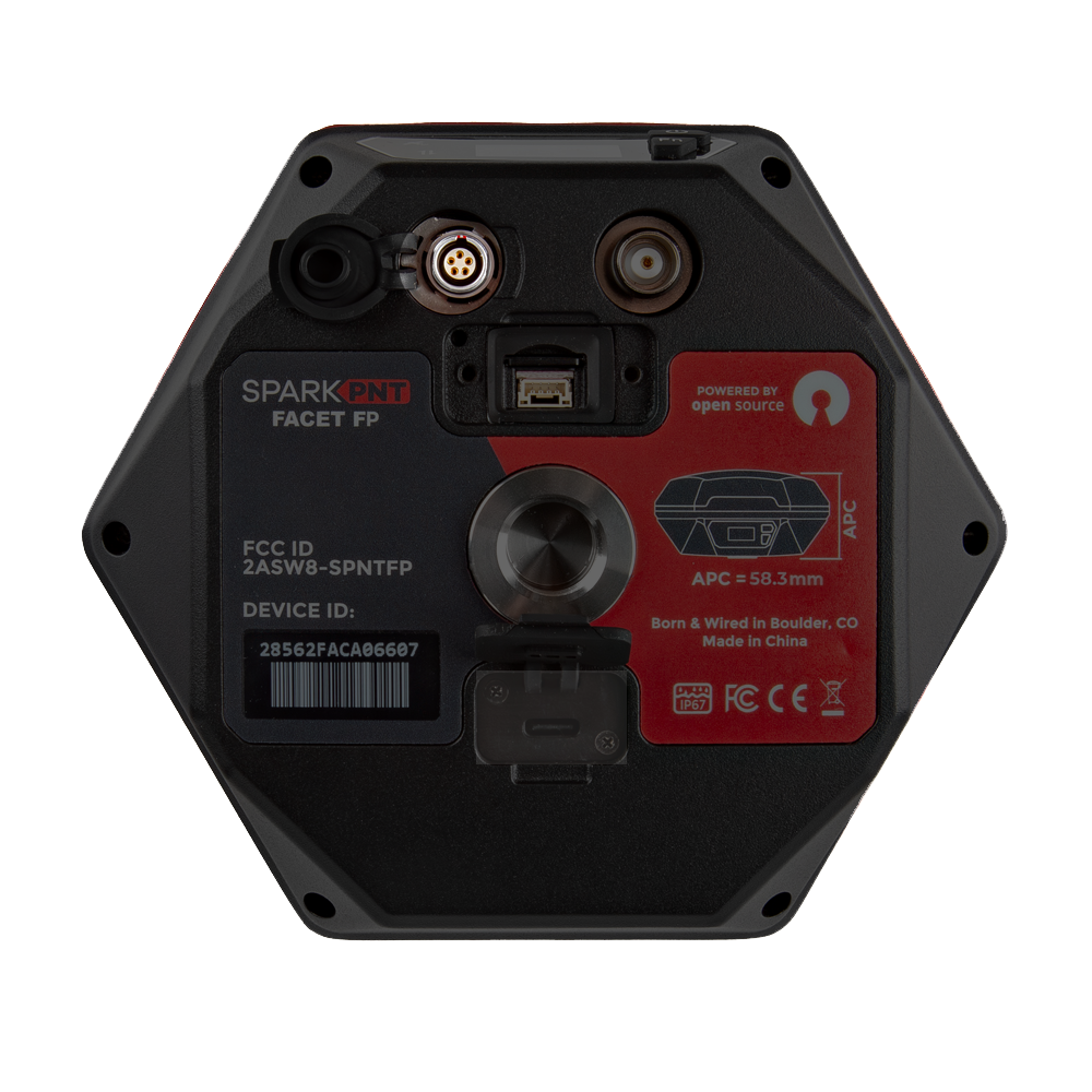
The pin connections from the SparkPNT FPL-T to the wires in the interface cable, are listed below:
- Red:
VIN(6-20V) - Yellow:
RX - White:
TX - Black:
GND
USB Connector
Users can access the USB-C port, under the rubber cover on the bottom of the FPL-T.
Don't forget to fully close the rubber cover. The enclosure's IP67 ingress rating (waterproof to 1 meter, for up to 30 minutes), is only valid when the all the covers are sealed.
- In most cases, the USB-C post will be accessed to charge the battery. The FPL-T supports PD charging up to 10W; this allows a fully discharged FPL-T to be charged to 100% in a few hours.
- For more advanced users, this port can be utilized to configure the FPL-T, update the device and GNSS receiver firmware, and/or retrieve a diagnosis report for troubleshooting.
When connecting to the USB interface of the SparkPNT FPL-T to a computer, users will need to install a USB driver to access the data or configure any settings.
The USB drivers for the CH342 USB-to-Serial converter can be downloaded from the manufacturer's website.
- Windows: Download Page for
CH343SER.EXE - MacOS: Download Page for
CH341SER_MAC.ZIP - Linux: A USB driver is not required for most Linux based operating systems
SMA Connector
The built-in LoRa radio is primarily utilized to transmit and receive RTK corrections. For the 1W LoRa transciever to function, users need to connect the 2dBi 915MHz whip antenna to the SMA connector on the bottom of the FPL-T. When not in use, the rubber cover should be replaced on the connector to maintain the IP67 ingress rating of the enclosure.
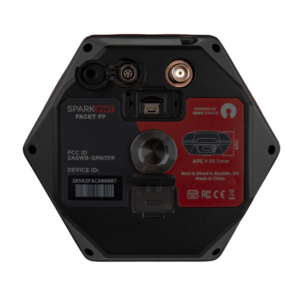
Don't forget to replace the rubber cover. The enclosure's IP67 ingress rating (waterproof to 1 meter, for up to 30 minutes), is only valid when the all the covers are sealed.
Specifications
Below are the full specifications for this device:
- LG290P GNSS Receiver
- Supported Frequency Bands
- GPS: L1C/A, L1C, L2C, L5
- GLONASS: L1, L2
- Galileo: E1, E5a, E5b, E6
- Beidou: B1I, B2I, B3I, B1C, B2a, B2b
- QZSS: L1C/A, L1C, L2C, L5, L6
- NavIC: L5
- SBAS: L1
- Accuracy:
- Autonomous:
- Horizontal: 0.7m
- Vertical: 2.5m
- RTK:
- Horizontal: 8mm + 1ppm
- Vertical: 15mm + 1ppm
- Autonomous:
- Time to Fix: <28s
- Supported Frequency Bands
- Antenna
- L1, L2, L5, L6
- Gain: ≥2.3dBi
- APC (NGS Calibrated):
- L1: 65.7mm
- L2/L5: 50.9mm
- Average: 58.3mm
- WiFi, BLE
- 2.4GHz
- L1, L2, L5, L6
- Enclosure
- Ingress Protection: IP67 (1m of water for 30 minutes)
- Materials: Aluminum body w/ plastic cap
- Single push button control
- Three LED indicators
- USB-C port w/ rubber cover
- Battery
- Specs: 7.2V 6800mAh (48.96Whr)
- Charging: up to 10W
- Run Time: 48hrs
- Dimensions: 71 x 71 x 147mm (2.8 x 2.8 x 5.8in)
- Weight: 423g (0.93 lbs)