Repair Manual
This guide is provided to assist users that would like to repair or replace certain components on the board.
Open the Enclosure
The FPL-T can be opened by removing the six Phillips head screws located on the bottom of the enclosure's antenna cap.
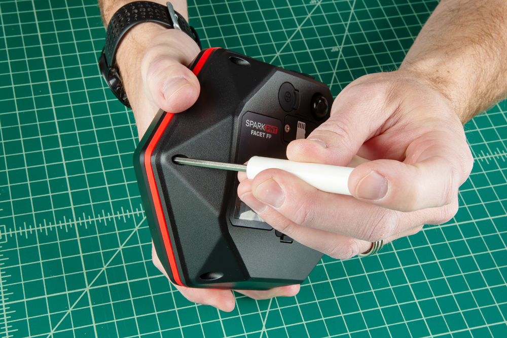
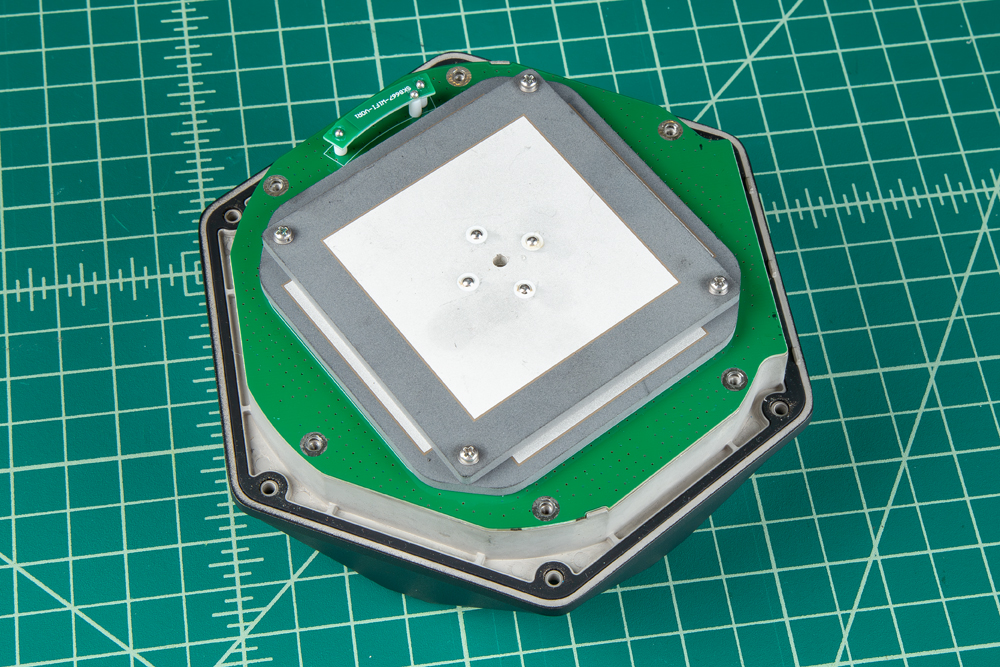
Once unscrewed, the plastic cover should come right off, exposing the ceramic GNSS and WiFi/BLE antennas underneath.
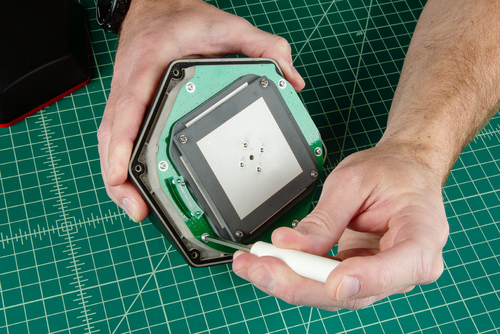
Remove the Antenna Stackup
Once the antenna cover is removed, users can access the six Phillips head screws holding the antenna PCB in place.
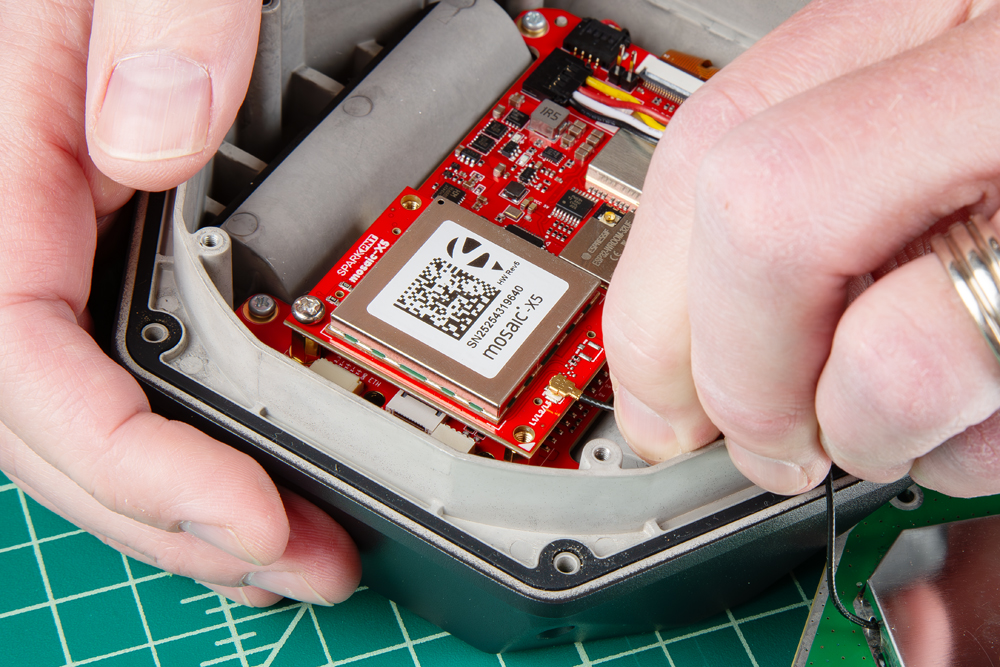
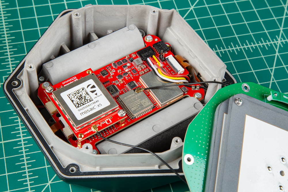
With the screws removed, gently and very carefully lift the upper PCB antenna off the enclosure. There are two U.FL cables underneath the antenna, users will need to disconnect the cables from the mainboard PCB and GNSS Flex module.
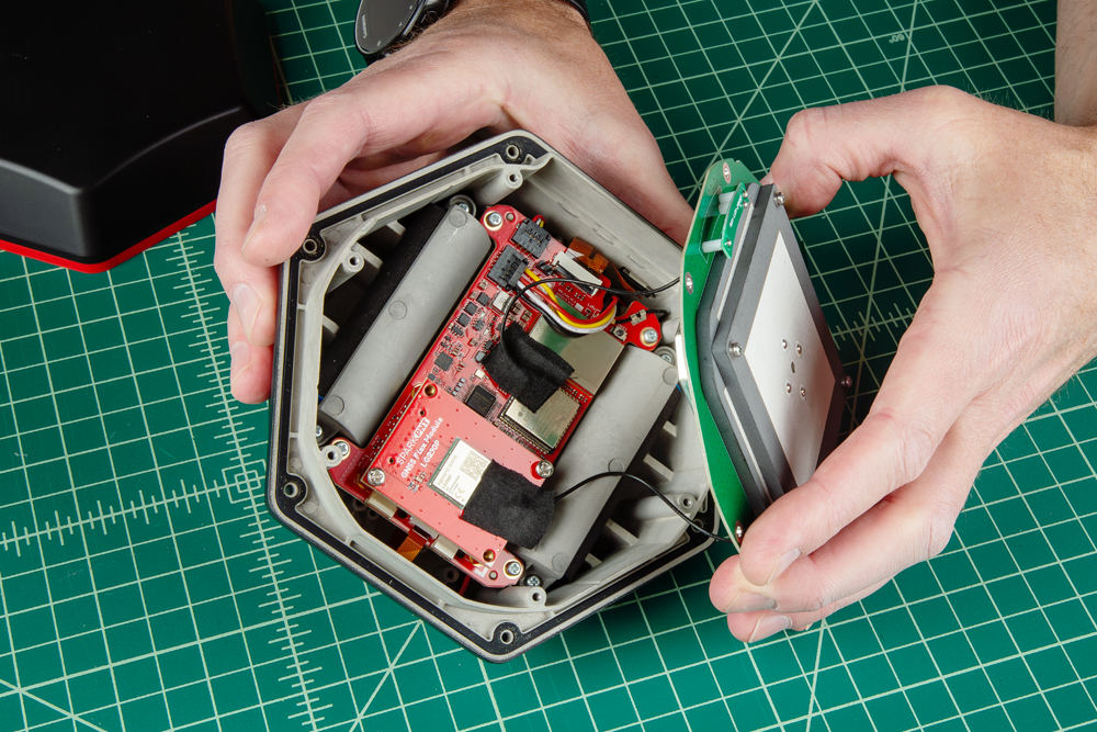
Be careful removing the PCB as there are U.FL cables attaching the antenna to other components.
The U.FL connectors are held in place with a piece of tape, which must be removed to access them. Carefully disconnect the U.FL cable, users may want to use a U.FL tool to avoid damaging the connection.

Swap Antenna
With the antenna element removed, users can replace the part as necessary.
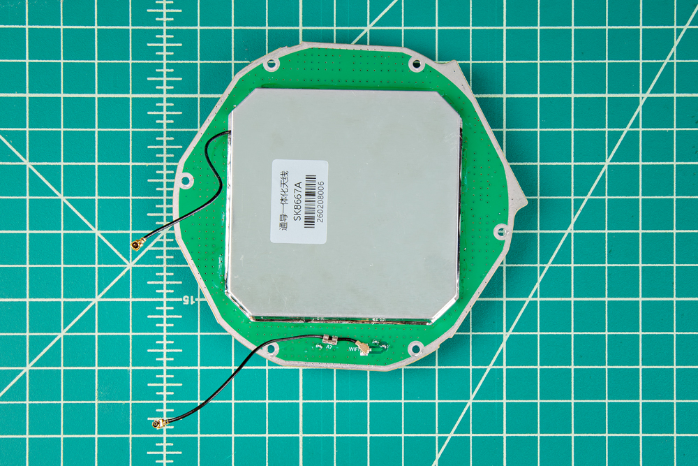
- The U.FL cable for the GNSS antenna will lead directly to the large metal cover of the antenna element.
- The U.FL cable for the WiFi/BLE antenna will lead directly to the PCB of the antenna element.
Reattach Antenna
Once you have replaced all the necessary components, reconnect the U.FL cables from the antenna element to the mainboard and GNSS Flex module.
The U.FL cable for the GNSS antenna that comes from the large metal cover of the antenna element, needs to be connected to the GNSS Flex module. Meanwhile, the U.FL cable for the WiFi/BLE antenna that is attached directly to the PCB of the antenna element, should be connected to the mainboard.
After the cable have been connected, replace the tape that was removed, this helps keep the cables in place.
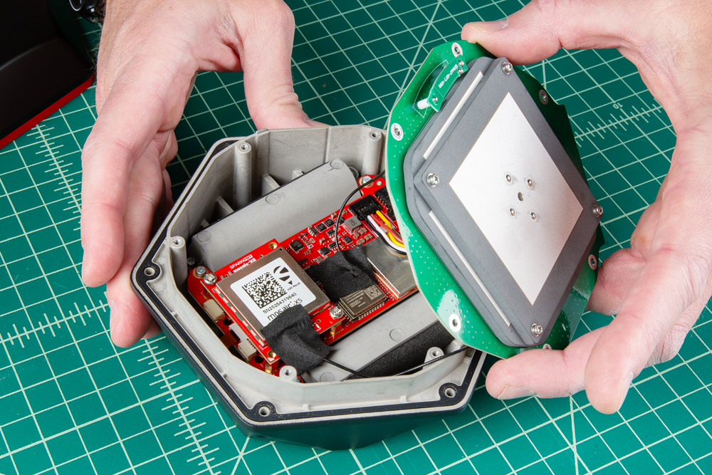
The PCB of the antenna element is cut to align directly with the edges of the enclosure
All that is left, is to secure the antenna and the enclosure cover with the screws that were removed earlier.
- Don't forget to attach the silicone bumper with the enclosure's cover.
- Be careful when threading these screws back into the cover. Over tightening or cross threading the screws into their holes, can strip out the screw head or eventually weaken the material fastening the screw.
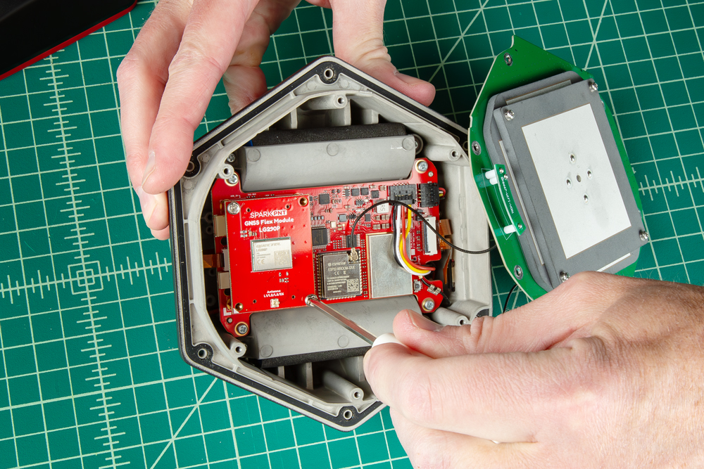
Remove the GNSS Flex Module
Once the antenna stackup has been removed, users can access the Phillips head screws holding the GNSS Flex module in place.
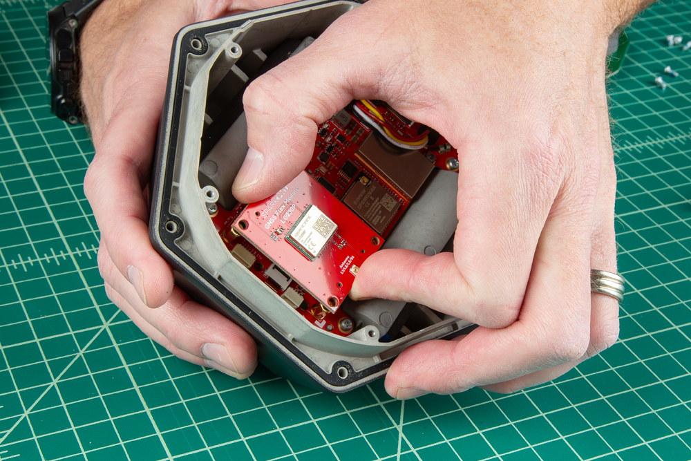
Swap Modules
For users that are just upgrading or replacing the GNSS Flex modules, carefully remove the GNSS Flex module. It is connected to the mainboard with two sets of 2x10-pin headers.
Once removed, attach the new GNSS Flex module. Be careful to note the alignment of the boards as the header pins are symmetric. The alignment indicator on the GNSS Flex module (circled below), should be pointing away from the display/user interface.
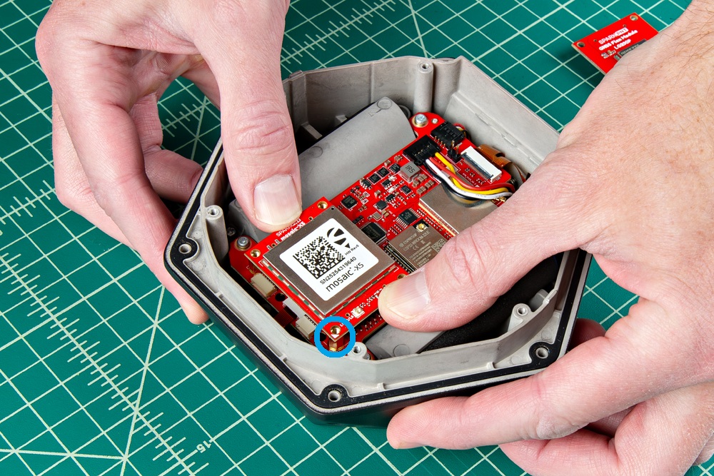
- Ensure the position of the alignment indicator on the GNSS Flex module, is pointing away from the display interface.
- Be careful when threading these screws back into the cover. Over tightening or cross threading the screws into their holes, can strip out the screw head or eventually weaken the material fastening the screw.
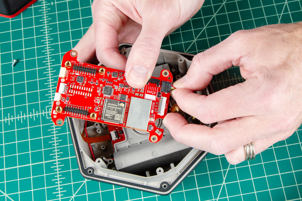
Remove the Mainboard PCB
Disconnect the four cables from the right-side and one cable on the left-side of the mainboard PCB. Then, remove the four Phillips head screws holding the mainboard PCB in place to free the board.
The UFL cable for the LoRa cable in secured in place with a wire crimp. Users should be able to slide the cable in-and-out of fixture, but be careful not to damage the components.
Replace the Mainboard PCB
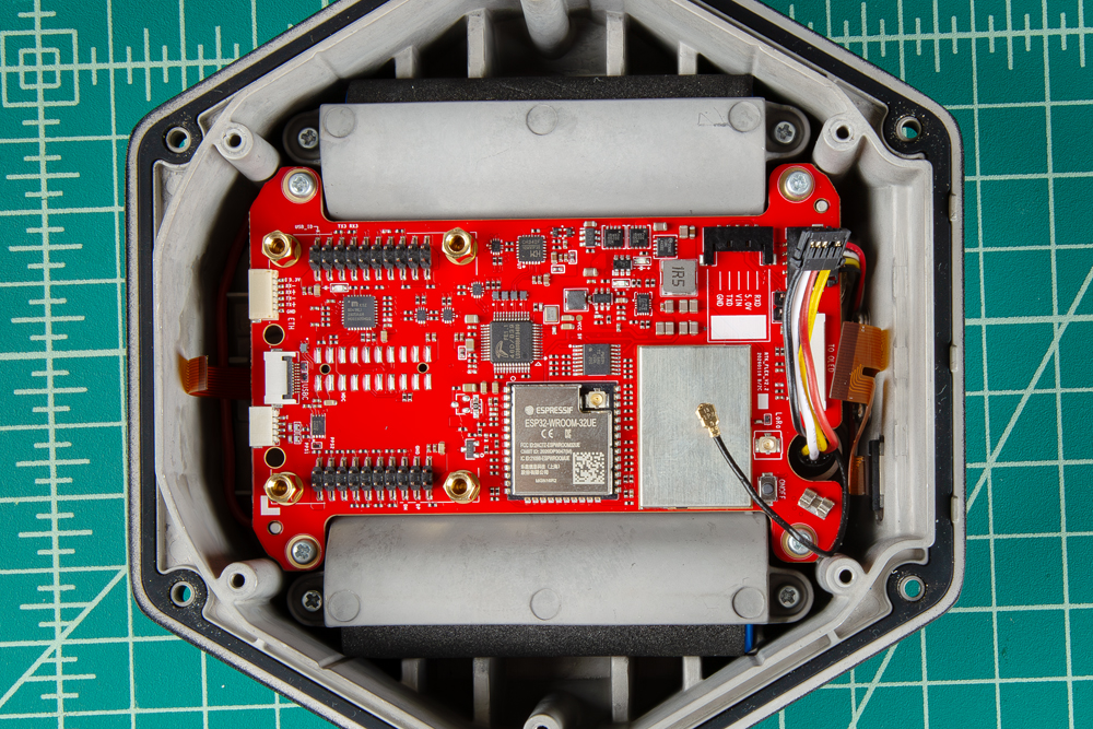
Once the unit has been serviced, we recommend reconnecting the cables to the mainboard before securing it to the enclosure. It will be easier to attach them before the board is in the enclosure
Once the cables have been attached, screw the mainboard back into the enclosure. Below, is an example of the components properly assembled, including the GNSS Flex module.
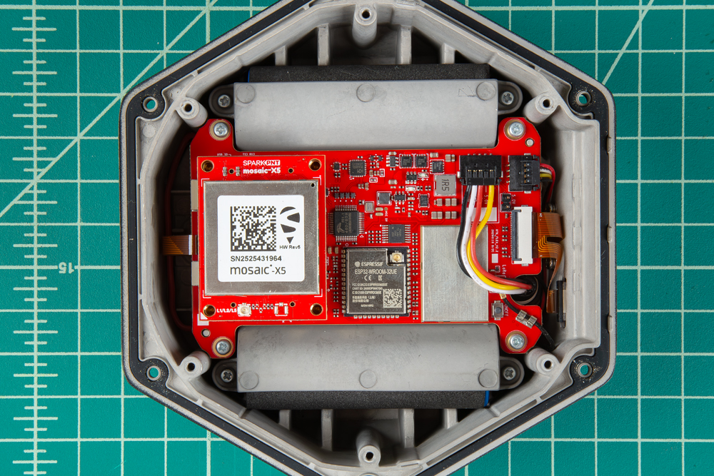
Be careful when threading these screws back in. Over tightening or cross threading the screws into their holes, can strip out the screw head or eventually weaken the material fastening the screw.
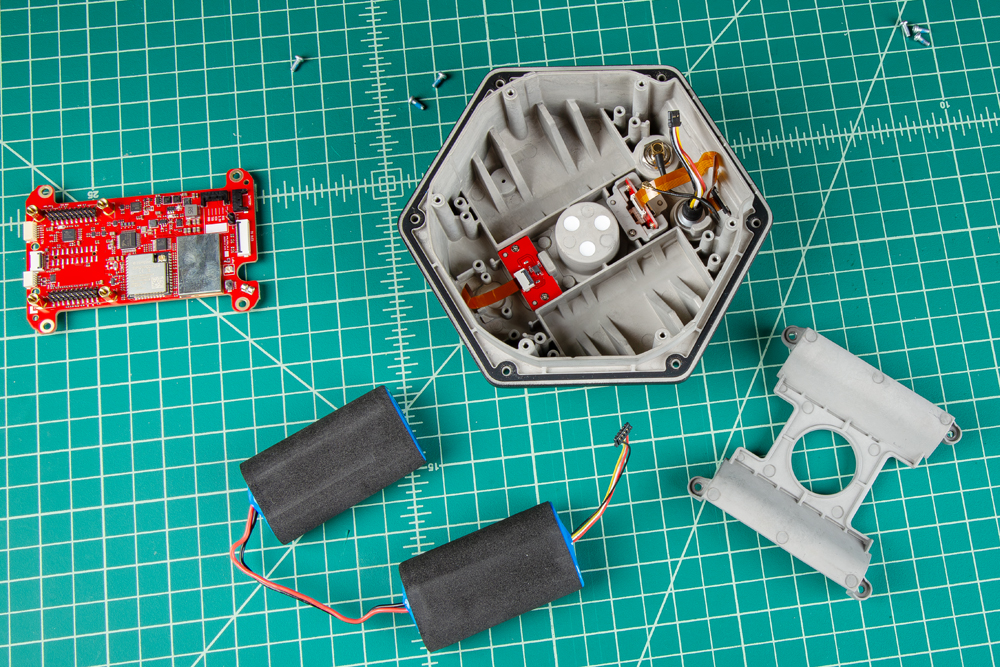
Remove the Battery Plate
With the mainboard out of the way, the battery cover can be removed. Remove the four Phillips screws from the batteries' retainer plate.
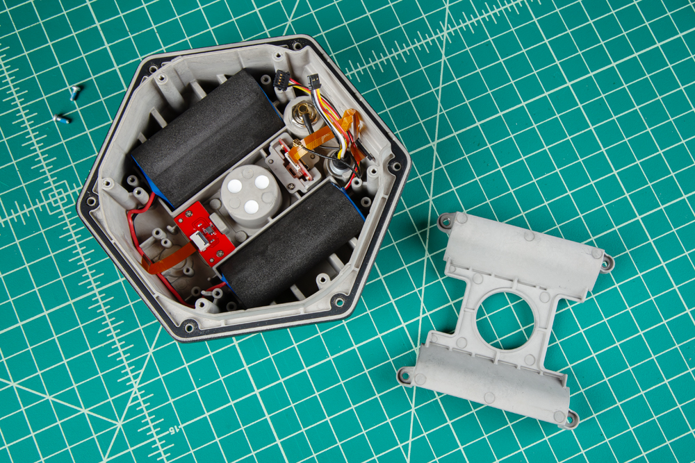
The 7.2V LiPo battery pack can be replaced and users can access the interface connections from the bottom of the SparkPNT FPL-T.
Be careful when threading the screws back into the cover. Over tightening or cross threading the screws into their holes, can strip out the screw head or eventually weaken the material fastening the screw.