Tilt Compensation
Configuration
From the rtk.local configuration webpage, open the Instrument Configuration drop-down menu. Here users can configure the APC (antenna phase center) and antenna height for the ARP (antenna reference point), so that measured positions are converted to reference the bottom of the survey pole.
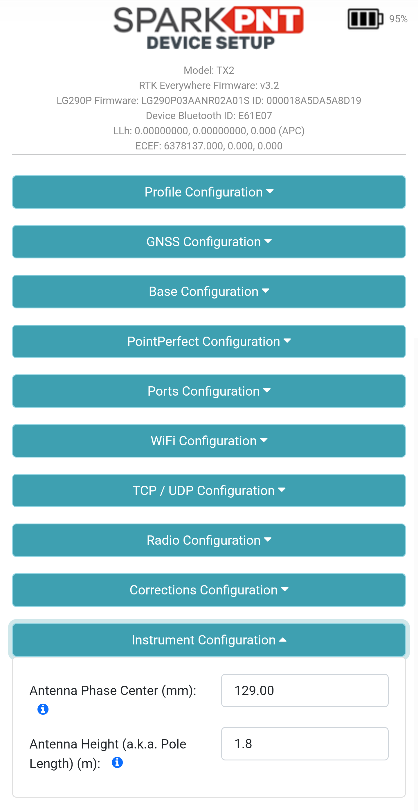
Instrument Configuration menu.There are two provided measurements:
- APC (mm): This is provided by default for the device. However, users can modify this with calibrated measurements for increased accuracy.
- Antenna Height (m): This is provided by the user, to convert the measured positions to reference the bottom of a surveying pole. The measurement should be provided in meters, with the length of the surveying pole from its bottom tip to the ARP (antenna reference point) of the mounted device.
After the desired settings have been changed, scroll to the bottom of the configuration webpage and click the Save Configuration button. Once the Success : All Saved message appears, reload the webpage to update the configuration settings.
Calibration & Initialization
Once configured, an initialization process is required to calibrate the IMU. As demonstrated in the videos below, user need to give the FPL-T a vigorous shake to initialize the calibration process.
- Shake to initialize calibration
- Swing the module back and forth (3-5sec)
- Rotate the device 90°
- Swing the module back and forth (3-5sec)
- Done
Accuracy
When configured and calibrated, the SparkPNT FPL-T fuses IMU sensor and GNSS RTK positioning data to deliver compensated position. The accuracy, displayed in the table below, should also be considered when implemented.
| Tilt Angle | Accuracy |
|---|---|
| 0° - 30° | 1cm |
| 30° - 60° | 2cm |