Equipment Overview
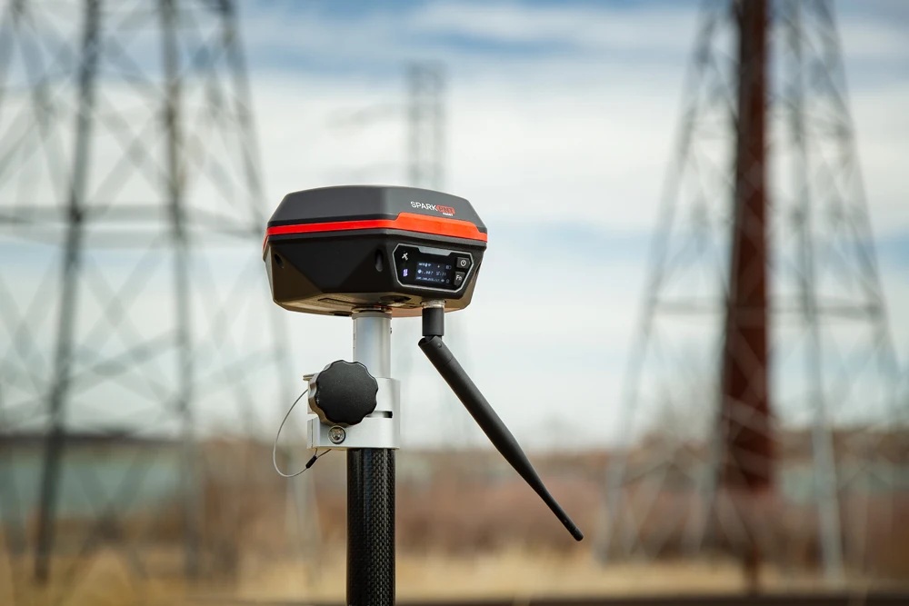
The SparkPNT FPL is a cost-effective, rugged, MFi certified, all-band GNSS RTK surveying unit. Unlike other high-precision RTK surveying devices, the GNSS receiver inside of SparkPNT FPL can be easily upgraded to meet your performance requirements, match the capabilities of your fleet, or when GNSS technology improves. The FPL provides Bluetooth and WiFi connectivity to any mobile device, including Apple iOS devices with its MFi certification. We have also included a built-in 1W 915MHz LoRa radio, to transmit/receive RTK corrections directly with other line-of-sight units up to 16km (>10mi) away.
- When it comes to fleet management, configuring another device is as simple as swapping out the SD card; gone are the days of needing to copy/paste credentials and settings.
- To start surveying positions, simply pair with the FPL on any smartphone or tablet, open your preferred GIS app, and access their NTRIP corrections service using the internet/cellular connection of your mobile device.
- The SparkPNT FPL can also operate as a base station, to broadcast RTCM corrections and function as an NTRIP Caster/Server.
- When working on a tight deadline, users can also implement our
Base Assistfunction to automatically configure the base station's position in minutes. Great for scenarios, where only relatively accuracte measurements are required and not the absolute accuracy of their global position; such as surveying the layout of a building. - Using its WiFi capabilities, users can configure the FPL to operate as an NTRIP Caster/Server on a local WiFi network, be used as an access point, or even connect to another SparkPNT device directly using the WiFi 2.4GHz transceiver, great for regions where the 915MHz radio can't be utilized.
- When working on a tight deadline, users can also implement our
With built-in HAS reception on the FPL, users can operate in remote locations with no cellular or internet access. These corrections require about 15 minutes for the PPP algorithm to converge on a solution that has better than 20cm (8 inches) of accuracy. The corrections are free, provided over the Galileo GNSS constellation, and have global coverage. If internet access is available at your worksite we still recommend using land-based corrections for much better accuracy and faster RTK Fix times. Consider HAS to be a slow but ok backup when there is no internet.
This is all housed in an IP67 rated enclosure and constructed with an anodized die-cast magnesium body and a fracture resistant fiberglass dome. The entire kit ships in a hard-sided case with all the accessories needed to start work. We've even included extra silicon bumpers to facilitate unit identification and repair.
Tilt compensation is not supported by this device.
Parts List
The SparkPNT FPL comes shipped inside a hard-sided carrying case with all the accessories need for users to get right to work. Below, is an overview of all the included parts:
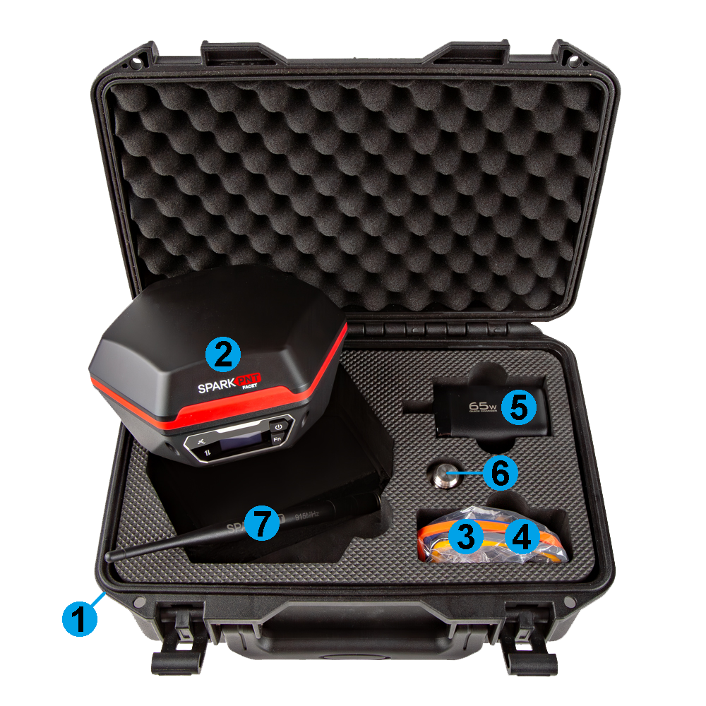
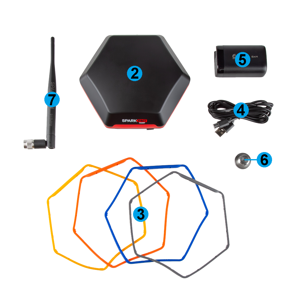
- Carrying Case
- SparkPNT FPL
- Silicone bumper set
- USB-C Cable
- USB-C Charger (65W)
- Thread Adapter (1/4" to 5/8")
- LoRa Antenna (915MHz, 2dBi)
Carrying Case
The FPL comes with a hard-sided case that includes two holes for pad locks (with shackles up to 6mm in diameter) to keep your equipment secure.
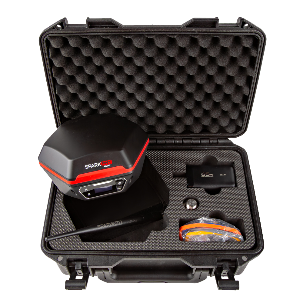
We recommend limiting the shackle diameter to less than 6mm; a 1/4" (6.35mm) shackle will not fit without modifying the case.
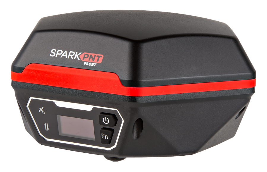
Enclosure
The FPL features a die-cast magnesium body with a fracture resistant fiberglass dome. The enclosure is IP67 rated and is waterproof to 1 meter, for up to 30 minutes.
The device should not be considered IP67 waterproof if the LoRa antenna is attached or any of the ports on the bottom are exposed. The rubber covers need to be fully seated, cover for the JST/SD card slot attached, and the TNC connector capped for the enclosure to qualify for the IP67 ingress protection rating.
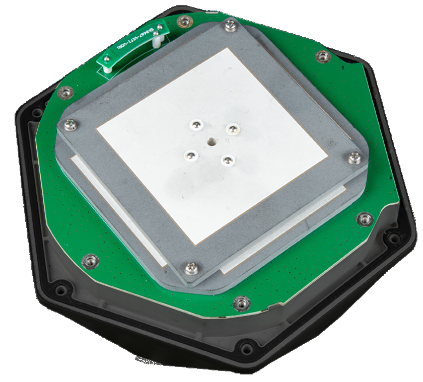
GNSS Antenna
Underneath its fiberglass dome, the FPL features a specially tuned multi-frequency (L1/L2/L5) GNSS antenna combined with a 2.4GHz BT/WiFi antenna.
Don't forget that GNSS signals are weak and can't penetrate buildings or dense vegetation. The GNSS antenna should have an unobstructed view of the sky.
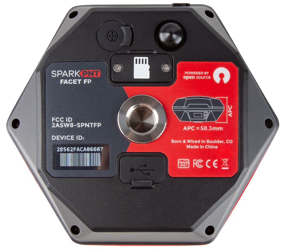
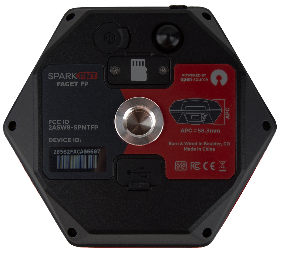
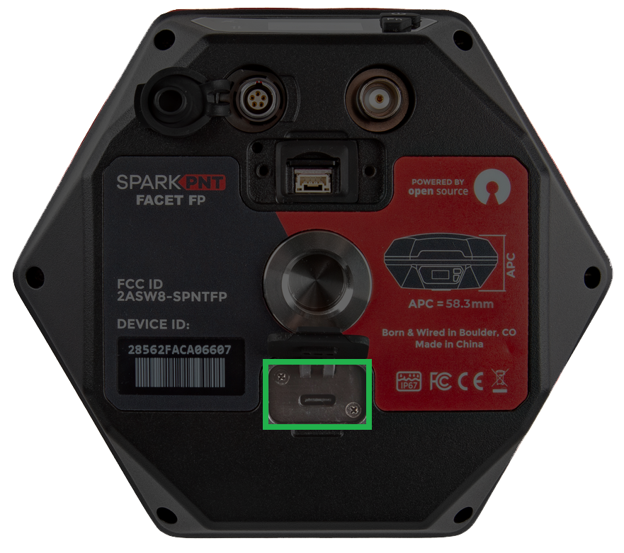
APC and NRP
The threaded mounting point at the bottom of the device serves as the device's ARP (antenna reference point). The FP has been calibrated by the NGS and the ANTEX and ANTINFO files are available.

The distance between the ARP on the FPL to the L1 APC (antenna phase center) is 65.7mm and 50.9mm to the L2/L5 APC. When calculating the total instrument height (pole length + APC), it is recommended to use the average between the L1 and L2 APCs which is 58.3mm. A common pole length is 1.8m, with an APC of 58.3mm the total instrument height is 1.858m. Enter this value into your GIS app to obtain the altitude of the point at the tip of the pole rather than the altitude at the antenna element.

The display serves as the device's NRP (north reference point).
Mount Point
The bottom of the FPL features a standard 5/8"-11 TPI threaded mount point. This is commonly found on surveying equipment and is compatible with most surveying poles. For additional mounting options (ie, camera camera mounts and tripods), the kit includes a 1/4" adapter.
The center of the threaded insert, on the plane of the device's base, serves at the ARP (antenna reference point) for the device.
Power
To power on the device, hold the () power button for a few seconds: the device will illuminate the display and beep once. To power down the device, hold the () power button for a few seconds: the device will show 'Shutting Down...' and beep three times.
Battery and Charging
-
Battery Charging - The FPL supports standard USB charging and can be charged from nearly any device that has a USB port. A red LED on the front display will turn on during charging and turn off when complete. A fully dead battery will charge in about 24 hours.
-
Battery Capacity - The FPL includes a 7.2V 6.8Ahr (48.96Whr) battery. This should allow the device to run continuously for more than 50 hours, in worst-case conditions.
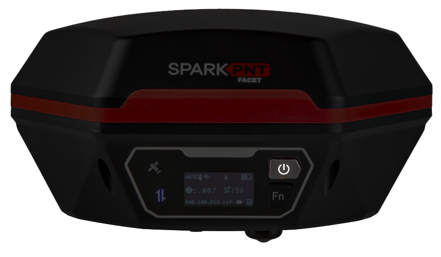
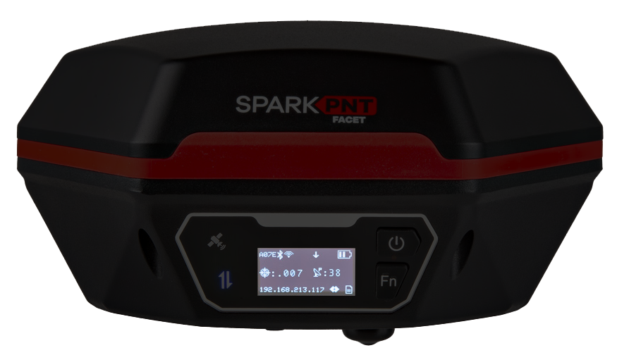
OLED Display
The user interface features a 1-inch high-contrast OLED display, three status LED indicators, and two user buttons. The display is used for a variety of status indicators and provide a means to navigate the configuration menu. See the Display section for more information.
The user interface also serves at the NRP (north reference point) for the device.
Buttons
There are two user buttons that can be used to turn the FPL on /off or navigate the menus displayed on the OLED screen.
- Power the device on or off:
- Hold the () power button for a few seconds: the device will illuminate the display and beep once. To power down the device, hold the () power button for a few seconds: the device will show 'Shutting Down...' and beep three times.
- Navigate menu:
- Open menu: From the main screen, press the (Fn) function button once to open the navigation menu.
- Move down/next option: Press the (Fn) function button navigate down to the next option on the menu of the OLED display.
- Select option/navigate into the sub-menu: Press the () power button to select an option or navigate into its sub-menu.
Indicators
The FPL also features three LED status indicators and an internal buzzer for audio feedback to the user.
Status LEDS
There are three LED status indicators on the front of the FPL.
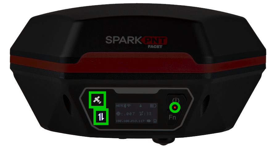
- The GNSS icon () indicates the GNSS pulse-per-second.
- The green LED will blink once per second when a GNSS fix is achieved.
- The Connection icon () indicates the Bluetooth connection status.
- The blue LED blinks once per second while waiting for a connection.
- The blue LED will turn solid once a Bluetooth connection is made.
- The Battery charge LED is located below the power button.
- The red LED will illuminate when attached to a charger.
- The LED will turn off when charging is complete.
Buzzer
The FPL also includes an internal buzzer that provides audio feedback for the user. The following prompts are provided:
- Power On: Beep once
- Power Off: Beep three times
- On versions that have tilt, the buzzer will beep periodically when tilt compensation is active.
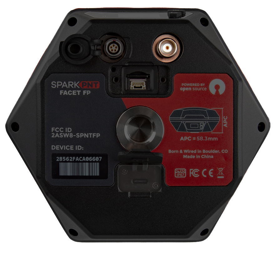
Data/Communication Connections
There are multiple data and communication connectors on the bottom of the FPL: microSD card slot, locking JST data interface, Lemo-compatible data interface, USB-C, and TNC. The microSD card slot and JST connector are both enclosed under the same cover.
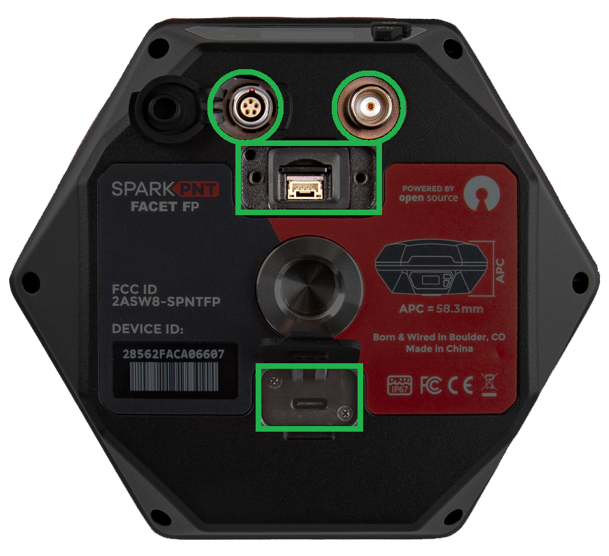
The device should not be considered as IP67 waterproof if the LoRa antenna is attached or any of the ports on the bottom are exposed. The rubber covers need to be fully seated, cover for the JST/SD card slot secured, and the TNC connector capped for the enclosure to qualify for the IP67 ingress protection rating.
USB Connector
Users can access the USB-C port under the rubber cover on the bottom of the FPL.
-
The USB-C port is most commonly accessed to charge the battery. The FPL supports standard USB charging and can be charged from nearly any device that has a USB port. A red LED on the front display will turn on during charging and turn off when complete. A fully dead battery will charge in about 24 hours.
-
For more advanced users, this port can be utilized to configure the FPL, update the device and GNSS receiver firmware, and/or retrieve a diagnosis report for troubleshooting.
When connecting to the USB interface of the SparkPNT FPL to a computer, the device should automatically be detected as two COM ports. If the ports are not detected then users will need to install a USB driver to access the data or configure any settings.
The USB drivers for the CH342 USB-to-Serial converter can be downloaded below:
- Windows: Download Page for
CH343SER.EXE - MacOS: Download Page for
CH341SER_MAC.ZIP - Linux: A USB driver is not required for most Linux based operating systems
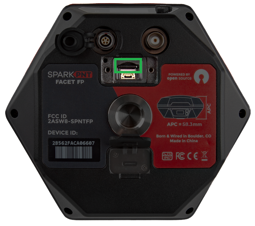
microSD Card
The microSD card slot and JST-GH connector are covered under the same access port. To access these interfaces, unscrew and remove the cover piece. Users can insert a microSD card that is formatted with FAT32 for cards up to 32GB, or exFat for cards up to 512GB. The SD card can be used to transfer user profiles between devices, log data points, and store diagnostic reports.
If a microSD card is detected, the FPL settings will be overwritten by the settings file on the card. This allows a 'golden card' to be used to reprogram a series of units and can be helpful for fleet management. A factory reset will clear the settings on the device and any setting file on the card.
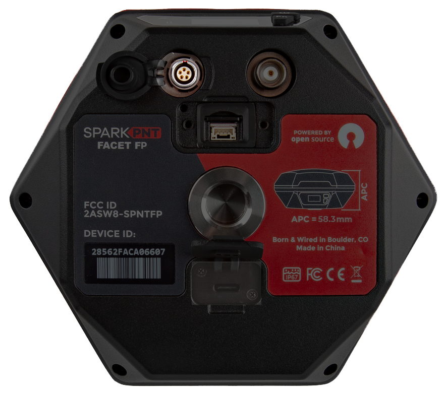
Lemo Connector
The 5-pin Lemo-style locking connector is provided to connect the SparkPNT FPL using RS232 level serial. The connector is compatible with the interface cable. This cable can be left permanently attached allowing the device to be deployed remotely while maintaining a connection for data retrieval and device configuration. The unit remains IP66 waterproof (protected against jets of water in all directions) but cannot be submerged with this cover open.
The pin connections from the SparkPNT FPL to the wires in the interface cable are listed below:
- Red:
VIN(6VDC to 20VDC) - Yellow:
RX- RTCM and configuration data into the device in RS232 serial. - White:
TX- NMEA and RTCM data output from the device in RS232 serial. - Black:
GND
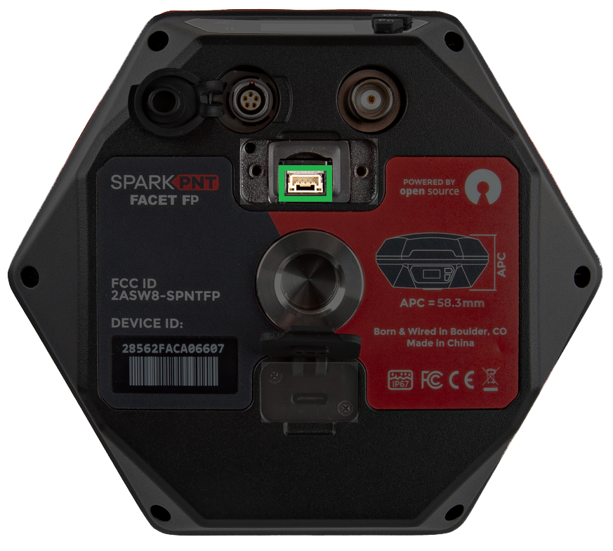
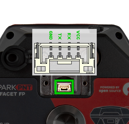
JST Connector
The JST interface allows communication over low-voltage TTL serial. This can be useful for connecting external high-power radios or embedded systems.
The JST connector is not recommended for long term installations as it allows water penetration. Use the Lemo-compatible connection for a waterproof connection.
The pin connections from the SparkPNT FPL to the JST wires in the JST-GHR cable are listed below:
- Red:
VIN(3.3VDC) - Green:
TX- NMEA and RTCM data output from the device in TTL serial. - Orange:
RX- RTCM and configuration data into the device in TTL serial. - Black:
GND
TNC Connector
The built-in LoRa radio is primarily utilized to transmit and receive RTCM corrections. For the 1W LoRa transceiver to function, users need to connect the 2dBi 915MHz whip antenna to the TNC connector on the bottom of the FPL and enable the radio setting. Running the radio without the antenna will not harm the unit, but ti is not recommended. When not in use, the rubber cover should be replaced on the connector to maintain the IP67 ingress rating of the enclosure.
The antenna screws on, finger tight, and can be used pointing straight down or at an angle as needed.
Specifications
- Antenna
- Enclosure
- Ingress Protection: IP67 (1m of water for 30 minutes)
- Materials: Magnesium body w/ fiberglass dome
- Dual button menu system
- Three LED indicators
- USB-C port
- microSD for data logging
- TNC for 1W LoRa Radio
- 5-pin Lemo-compatible connector for RS232 communication
- 4-pin JST connector for TTL communication
- Battery
- Specs: 7.2V 6800mAh (48.96Whr)
- Charging: 2W maximum
- Run Time: 50hrs
- Dimensions: 71 x 71 x 147mm (2.8 x 2.8 x 5.8in)
- Weight: 423g (0.93 lbs)