Repair Manual
This guide is provided to assist users that need to repair a unit.
We love DIYer's but products are covered by a 12 month warranty so check with us to see if a device is still covered or not. SparkPNT can also do out-of-warranty repairs for a very reasonable fee.
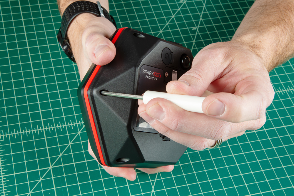
Remove the Dome
The FPL can be opened by removing the six Phillips head screws located on the bottom of the enclosure.
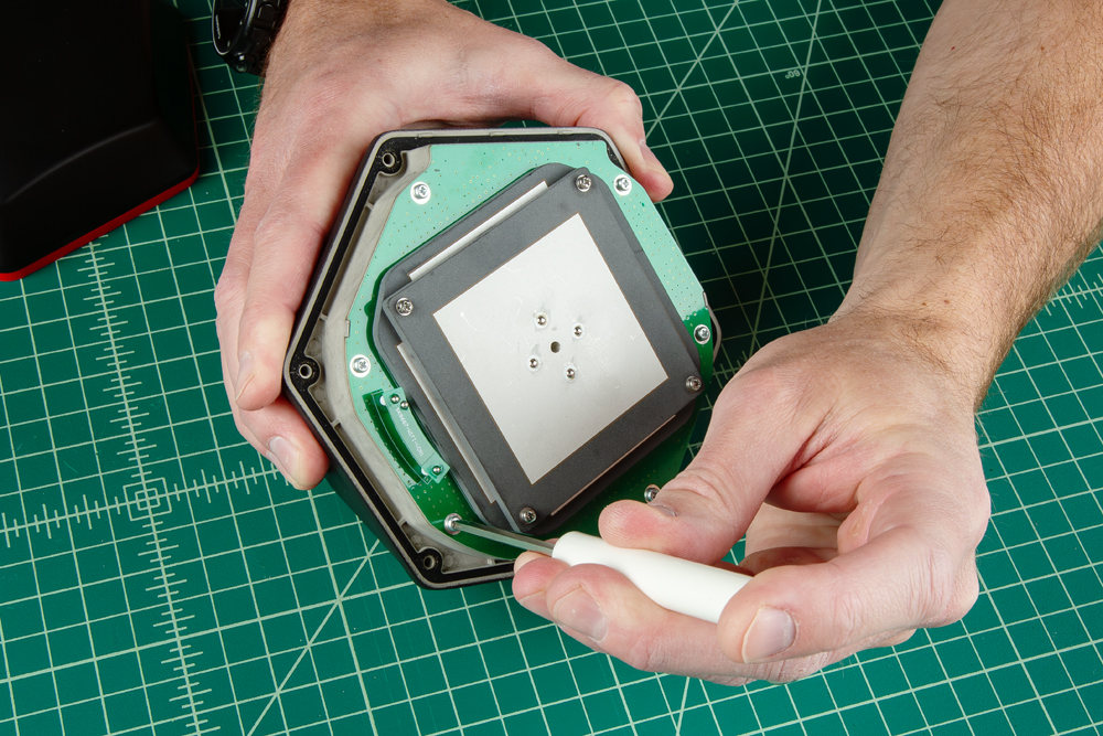
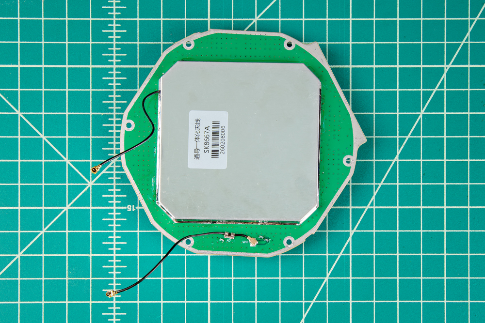
Once unscrewed, the plastic cover should come off, exposing the ceramic GNSS and WiFi/Bluetooth antennas underneath.
For aiding in identifying units, or in the case where the gasket has become dirty or damaged, the colored silicone gasket can be replaced once the enclosure is opened. With the dome removed, take off the old gasket and slot in a new one.
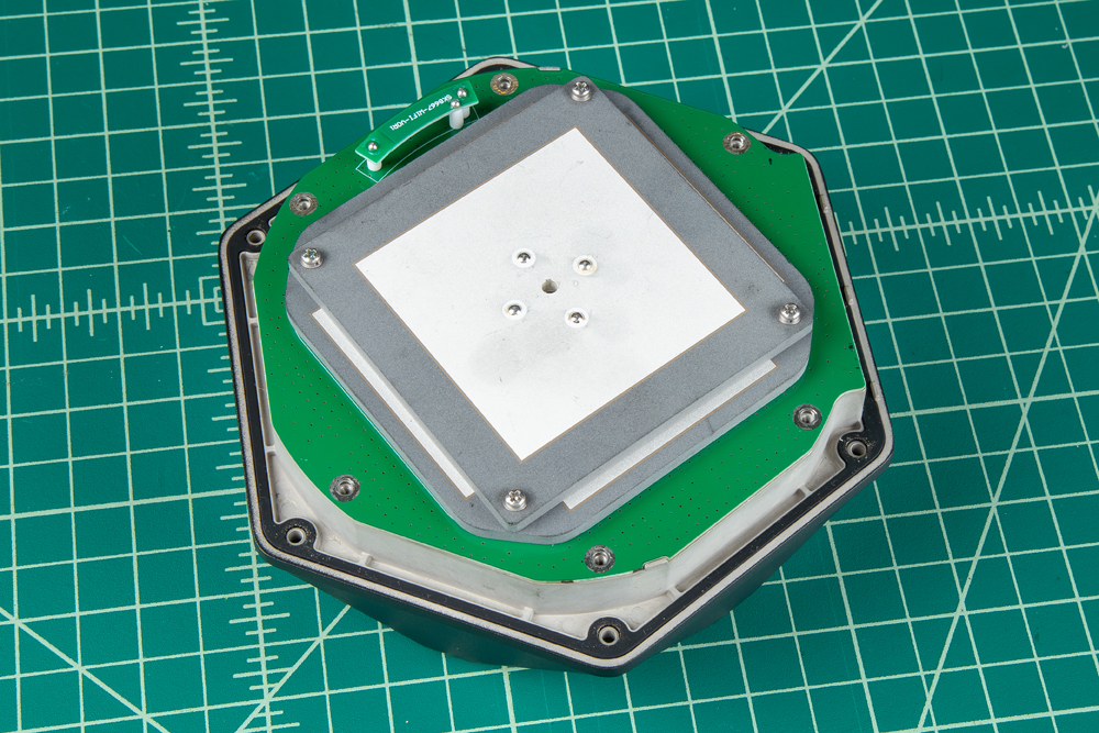
Remove the Antenna Stackup
Once the antenna cover is removed, users can access the six Phillips head screws holding the antenna PCB in place.
With the screws removed, gently and very carefully lift the upper PCB antenna off the enclosure. There are two U.FL cables underneath the antenna, users will need to disconnect the cables from the mainboard PCB and GNSS Flex module.
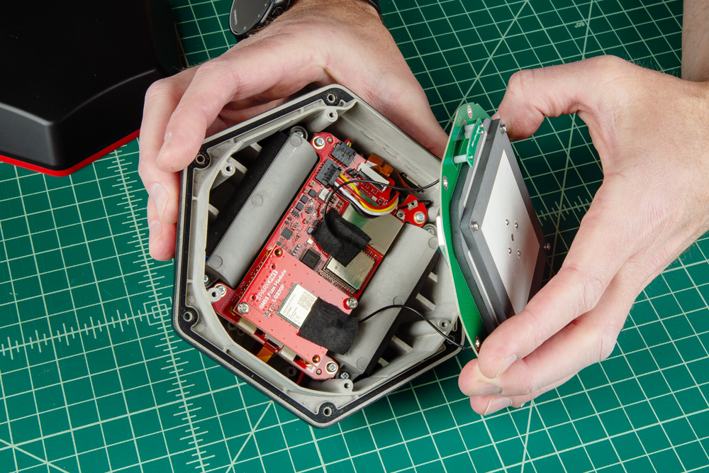
Be careful removing the antenna element as there are U.FL cables attaching the antenna to other components.
The U.FL connectors are held in place with a piece of tape, which must be removed to access them. Set the tape to one side so that it can be reused. Carefully disconnect the U.FL cable by lifting up on the black cable as close to the U.FL connector as possible. Users may want to use a U.FL tool to avoid damaging the connection.
Swap Antenna
With the antenna element removed, users can replace the part as necessary.
- The U.FL cable for the GNSS antenna will lead directly to the large metal cover of the antenna element.
- The U.FL cable for the WiFi/Bluetooth antenna will lead directly to the PCB of the antenna element.
Reattach Antenna
Once you have replaced all the necessary components, reconnect the U.FL cables from the antenna element to the mainboard and GNSS Flex module.
Align the U.FL cable above the connector. Once in place, gently press straight down with an index finger. There should be a satisfying snap when the connector engages.
The U.FL cable that comes from the large metal cover of the antenna element needs to be connected to the GNSS Flex module. Meanwhile, the U.FL cable for the WiFi/Bluetooth antenna that is attached directly to the PCB of the antenna element, should be connected to the mainboard.
After the cables have been connected, replace the tape that was removed, this helps keep the cables in place.
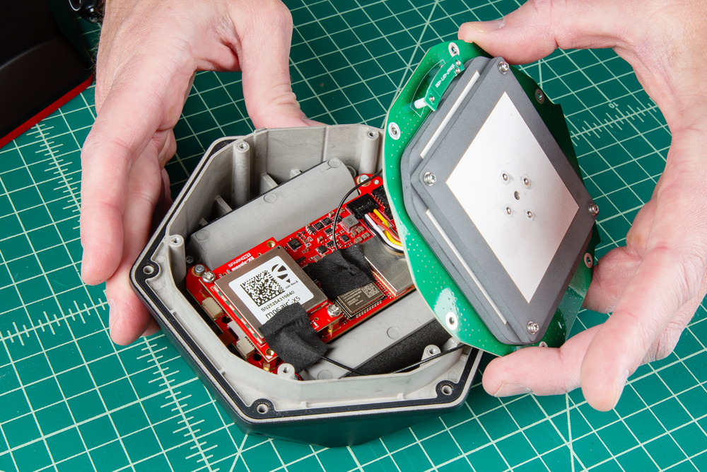
Rotate the antenna element until in sits flat against the enclosure. The PCB of the antenna fits in only one orientation.
Secure the antenna and the enclosure cover with the screws that were removed earlier.
- Don't forget to attach the silicone bumper with the enclosure's cover.
- Be careful when threading these screws back into the cover. Over tightening or cross threading the screws into their holes, can strip out the screw head or eventually weaken the material fastening the screw.
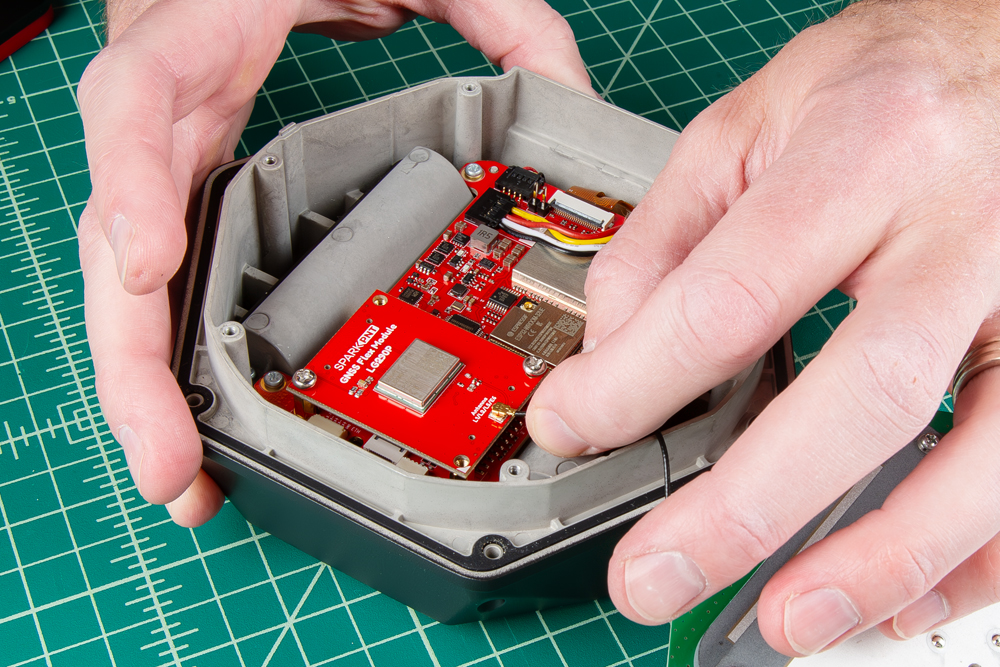
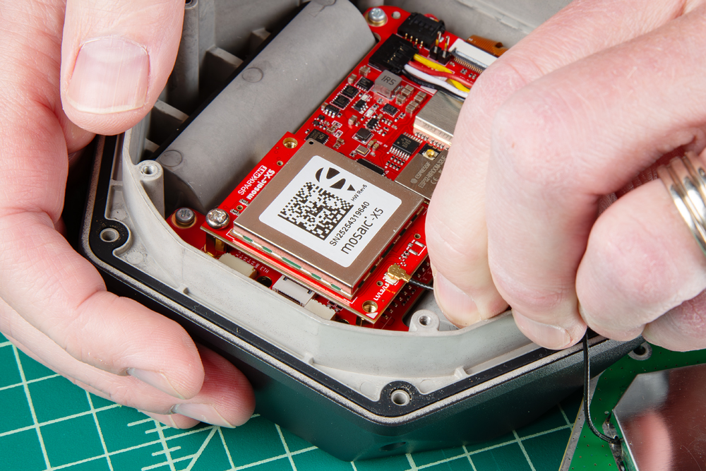
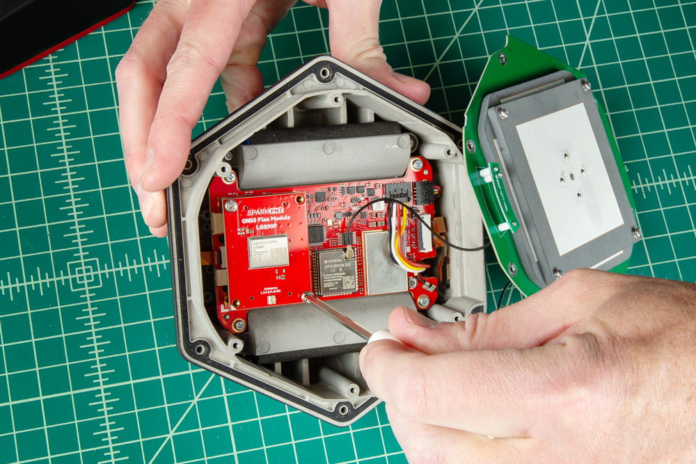
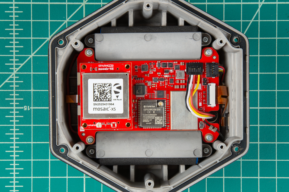
Remove the GNSS Flex Module
Once the antenna stackup has been removed, users can access the Phillips head screws holding the GNSS Flex module in place.
Swap Modules
For users that are just upgrading or replacing the GNSS Flex modules, carefully remove the GNSS Flex module. It is connected to the main board with two sets of 2x10-pin headers. Go slow! Rock the module edge back and forth until it starts to release, then pull straight up.
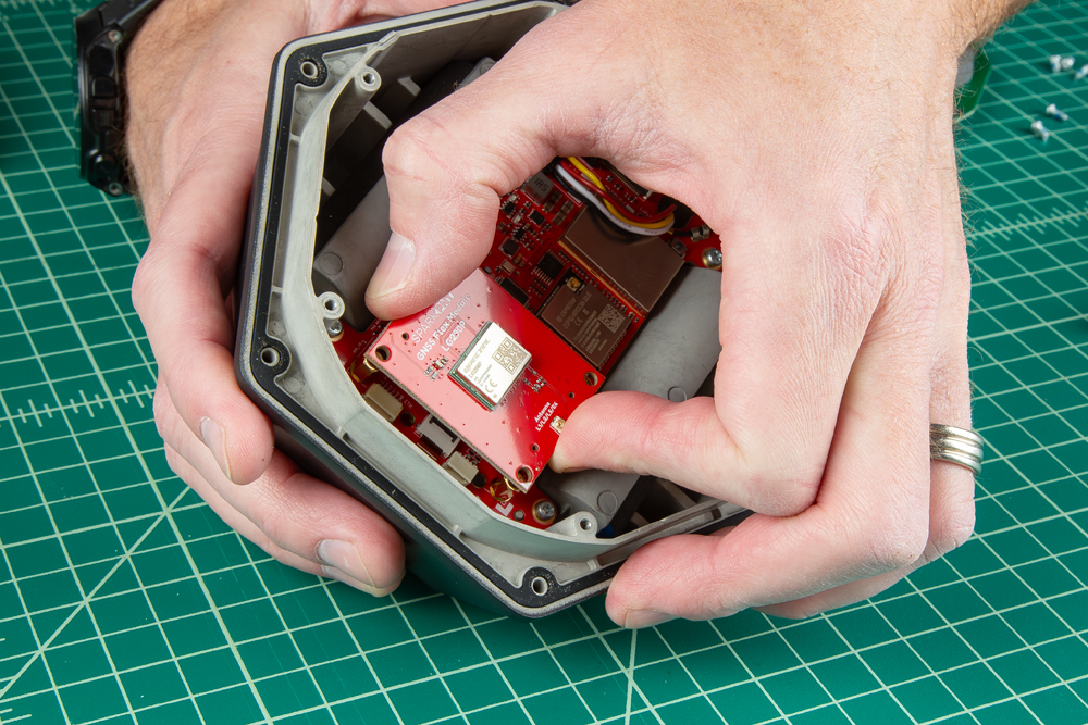
With the old GNSS module removed, insert the new GNSS Flex module. Be careful align the Flex module correctly as the header pins are symmetric. The alignment indicator on the GNSS Flex module (circled below), should align with the white indicator on the main board. Once aligned, press straight down until it is seated. Replace the screws to hold the module in place.
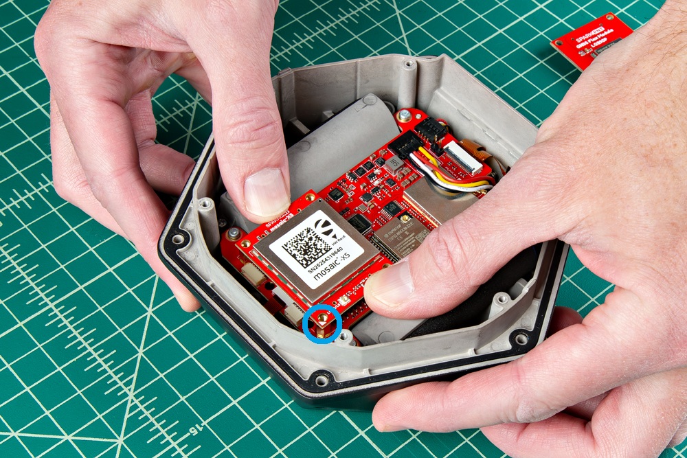
- Ensure the position of the alignment indicator on the GNSS Flex module, is pointing away from the display interface.
- Be careful when threading these screws back into the cover. Over tightening or cross threading the screws into their holes, can strip out the screw head or eventually weaken the material fastening the screw.
Remove the Mainboard PCB
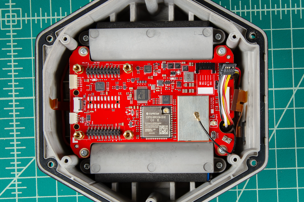
Use your fingernail to 'flip up' the back of the two ribbon connectors. This will release the ribbons. Use a pair of tweezers to remove the ribbons. Disconnect the colored wire cables with five pins by gently pulling on it. Leave the 4 pin colored wire cable in please.Remove the U.FL cable by sliding it sideways out of the crimp holder, then lifting slightly to release it from the U.FL connector. Then, remove the four Phillips head screws holding the mainboard PCB in place to free the board.
The U.FL cable for the LoRa cable in secured in place with a wire crimp. Users should be able to slide the cable sideways out of fixture. Be careful not to damage the cable or surrounding components.
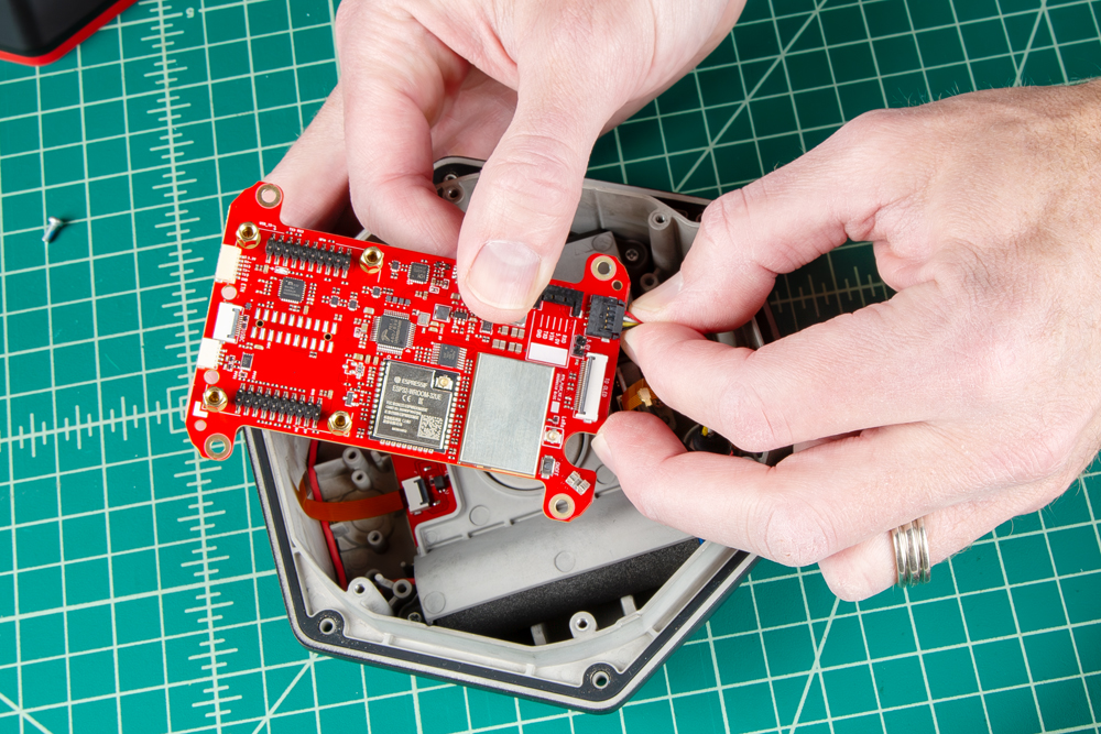
Above, once the mainboard has been unscrewed, pinch the remaining 4 pin colored wire connector with tweezers or fingers to allow it to release.
Replace the Mainboard PCB
Once the unit has been serviced, shown above, first reconnect the 4-pin colored wire connector by pressing it back into place. Now screw the mainboard back into the enclosure.
Once the mainboard is screwed down, use a pair of tweezers to insert the brown ribbon cables into their connectors. Using a finger or the handle of the tweezers, flip the latches down to secure the ribbon cables in their two connectors.
Reconnect the U.FL connector by lining the cable directly over the connector, then gently pressing down. There should be a satisfying snap when the connector engages. Slide the U.FL cable sideways into the cable silver cable clip.
Reconnect the 5 pin colored wire cable.
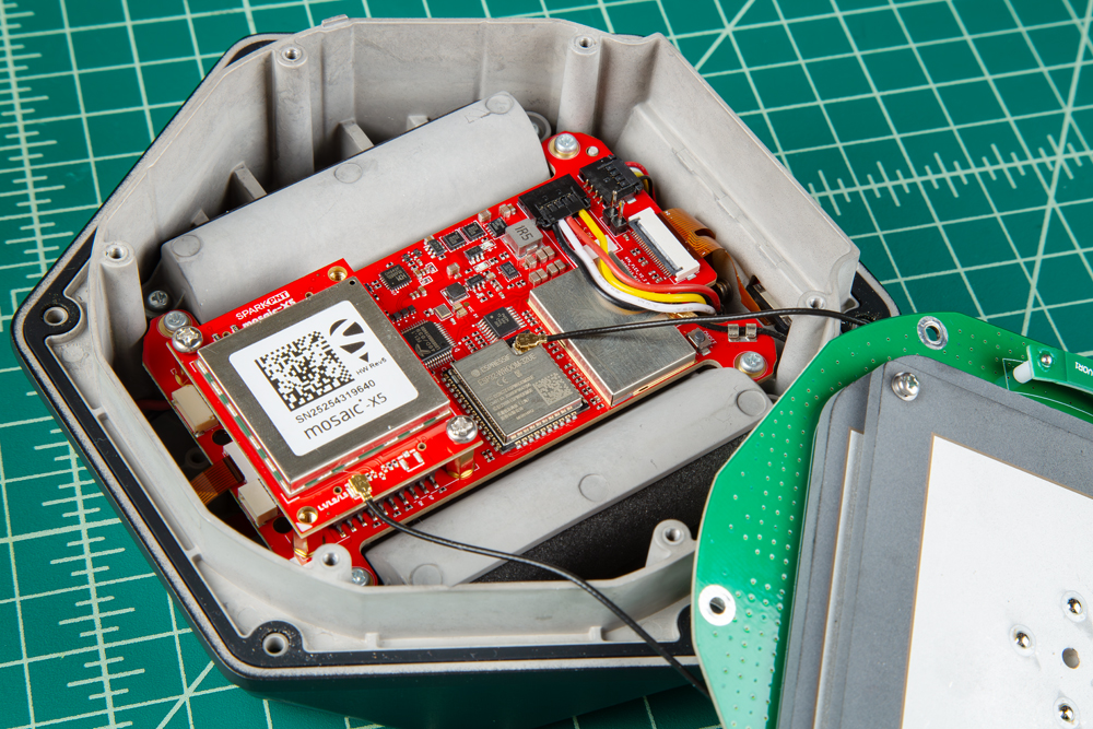
Above is an example of the components properly assembled, including the GNSS Flex module. Note the GNSS module needs two screws to hold it into place before re-attaching the antenna.
Be careful when threading these screws back in. Over tightening or cross threading the screws into their holes, can strip out the screw head or eventually weaken the material fastening the screw.
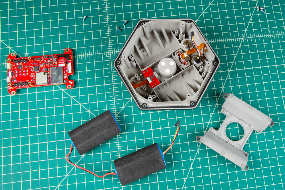
Remove the Battery Plate
With the mainboard removed, the battery cover can be removed. Remove the four Phillips screws from the battery retainer plate.
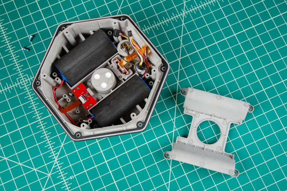
The 7.2V LiPo battery pack can be replaced and users can access the interface connections located on the bottom of the SparkPNT FPL.
Be careful when threading the screws back into the cover. Over tightening or cross threading the screws into their holes, can strip out the screw head or eventually weaken the material fastening the screw.