Quickstart Guide
The SparkPNT FPM is a cost-effective, rugged, MFi certified, all-band GNSS RTK surveying unit that can be upgraded and features a built-in RF transceiver. Its combination rover and high-precision base station functions are designed to optimize your on-site workflow.
Unlike other surveying devices, the GNSS receiver inside of SparkPNT FPM can be upgraded when GNSS technology improves, for additional capabilities, or just to match the rest of your fleet. The IP67 rated enclosure is constructed with an anodized aluminum body and a reinforced plastic cover. This entire kit ships in a hard-sided case, including additional accessories, and an appreciation sticker; extra silicon bumpers are also included to facilitate unit identification or serve as replacements.
Parts List
The SparkPNT FPM comes shipped inside a hard-sided carrying case with a few accessories to users get started. Below, is an overview of all the parts included with your purchase:
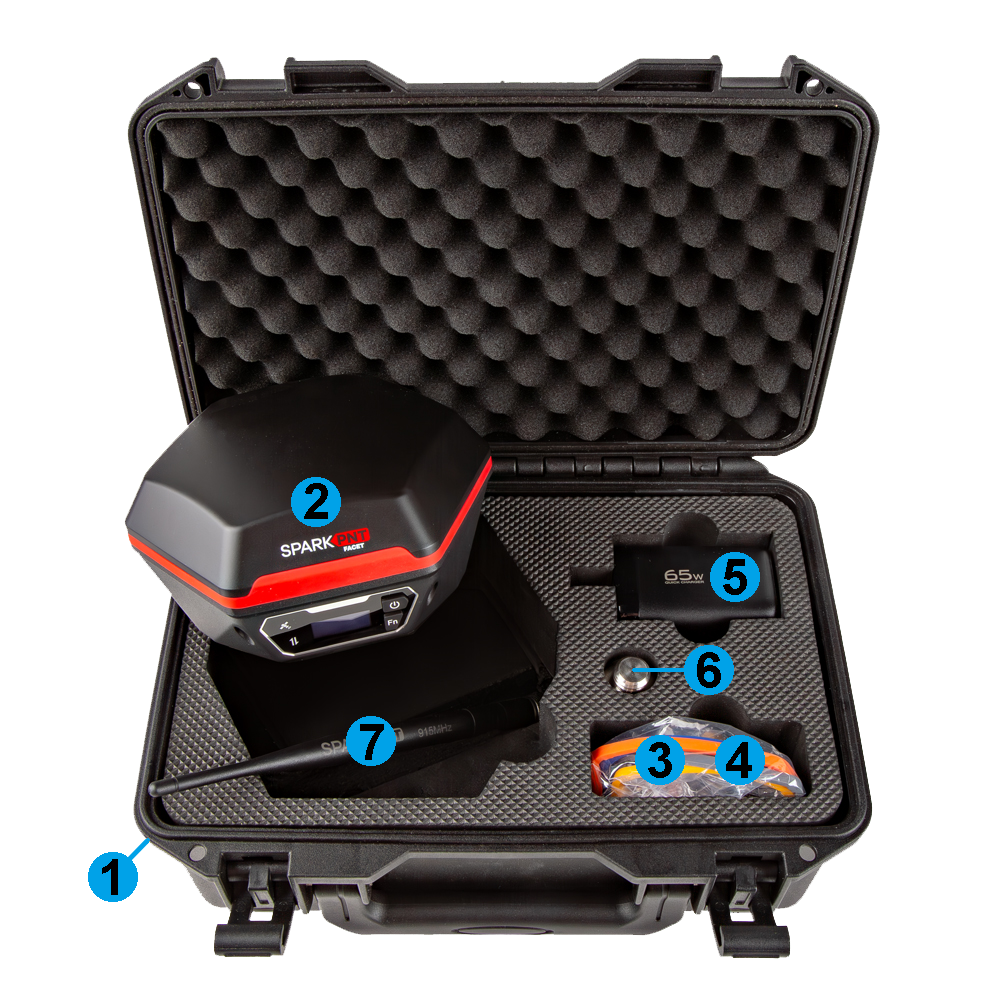
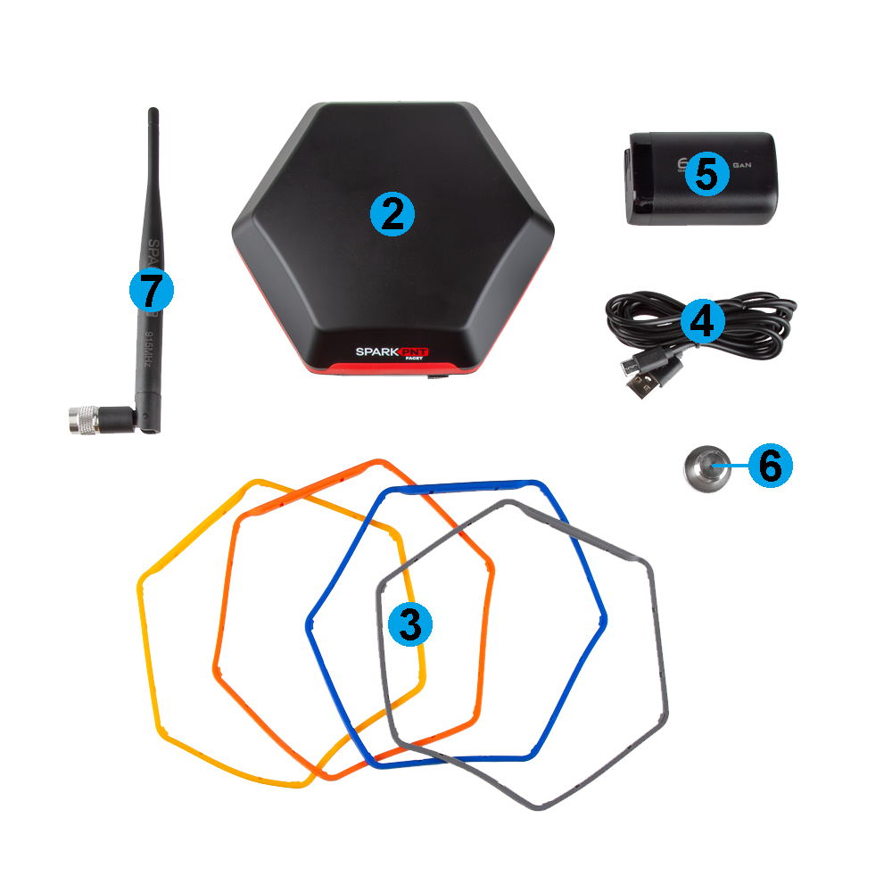
- Carrying Case
- SparkPNT FPM
- Silicone bumper set
- USB-C Cable
- USB-C Charger (65W)
- Thread Adapter (1/4" to 5/8")
- LoRa Antenna (915MHz, 2dBi)
Any available replacement parts are linked in the list above. Additionally, international adapter sockets can be purchased separately for the power adapter, if required.
Device Overview
Tilt compensation is not supported by this device.
Power
To power the device on or off, hold the () power button down for more than 3 seconds. When the device powers on, it will beep once; whereas, the device will beep three times when it powers down.
Battery
The FPM features a 49Whr battery and supports PD charging, up to 10W.
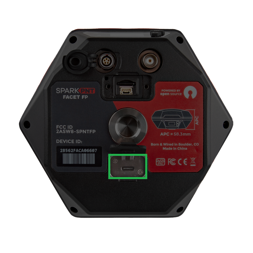
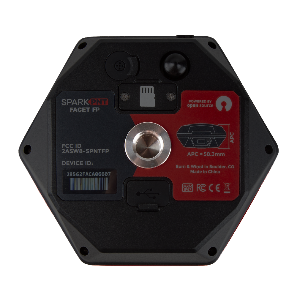
- Battery Charging - The FPM supports PD charging up to 10W; this allows a fully discharged FPM to be charged to 100% in a few hours. Users can access the USB-C port, under the rubber cover on the bottom of the device.
tip
Don't forget to fully close the rubber cover. The enclosure's IP67 ingress rating (waterproof to 1 meter, for up to 30 minutes), is only valid when the all the covers are sealed.
- Battery Capacity - The FPM includes a 7.2V 6.8Ahr (48.96Whr) battery. This should allow the device to run continuously for more than 50 hours, even in the worst-case conditions.
Connectivity
In order to get corrections or configure the device, users should pair the device with their phone. Double-tap the power button (press twice, within 1 second) to connect to your device.
BLE
To provide RTK corrections from an NTRIP caster (or server), view the device's position in real-time, and manage datapoints, it is best to utilize a 3rd party app on a mobile device. Users can then, pair the FPM to their mobile device with a BLE connection.
For a Bluetooth connection, follow these steps:
- Power the device on.
- Hold the () power button for more than 3 seconds. It will beep once, indicating it has turned on.
- Once the device has powered up; double-tap the power button (press twice, within 1 second).
- The device will beep twice indicating it is waiting for incoming connections.
- On your mobile device, connect to BLE device named
SparkPNT FPM-3AF1.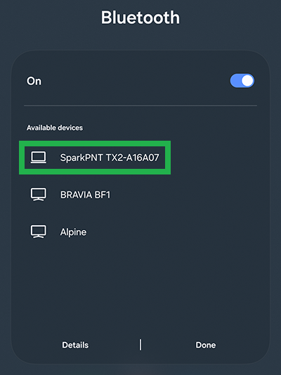
Pairing from an Android device. 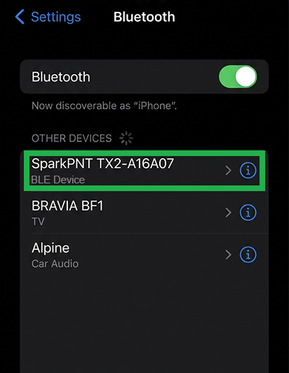
Pairing from an iOS device. - Once pair, you be able to access the device in your favorite GIS app.
WiFi
To change the configuration settings of the FPM, it is easiest to connect to the device's WiFi access point and pull-up the configuration webpage. Once connected, users can access the configuration webpage from a browser using the https://rtk.local URL address.
To get into browser configuration, follow these steps:
-
Power the device on.
- Hold the () power button for more than 3 seconds. It will beep once, indicating it has turned on.
-
Once the device has powered up; double-tap the power button (press twice, within 1 second).
- The device will beep twice indicating it is waiting for incoming connections.
-
On your mobile device, connect to WiFi network named
RTK Config. Upon connecting, your phone may warn you that the WiFi network is not connected to the internet. This is normal; stay connected and open a browser.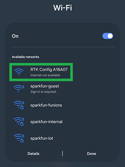
Connecting from an Android device. 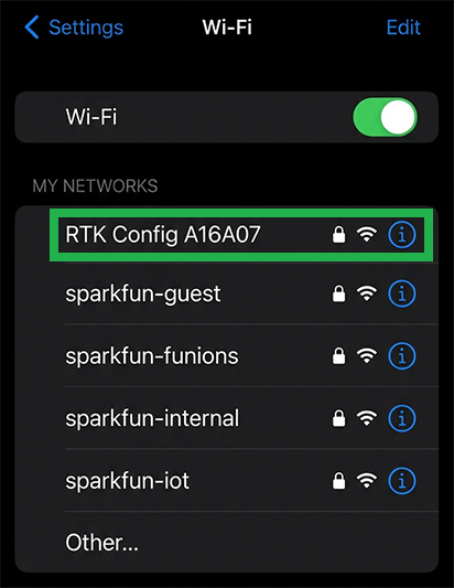
Connecting from an iOS device. warningIf you have problems, try disabling mobile/cellular data on your mobile device. The device or browser might be using the cellular connection for its internet access; however, we want to disable this setting to ensure that your mobile device remains on the WiFi access point for the browser.
-
Once the browser is opened, you should be automatically re-directed to the configuration webpage. If not, open a browser (Chrome is preferred) and type
http://rtk.localinto the address bar.https://rtk.local/http://rtk.local/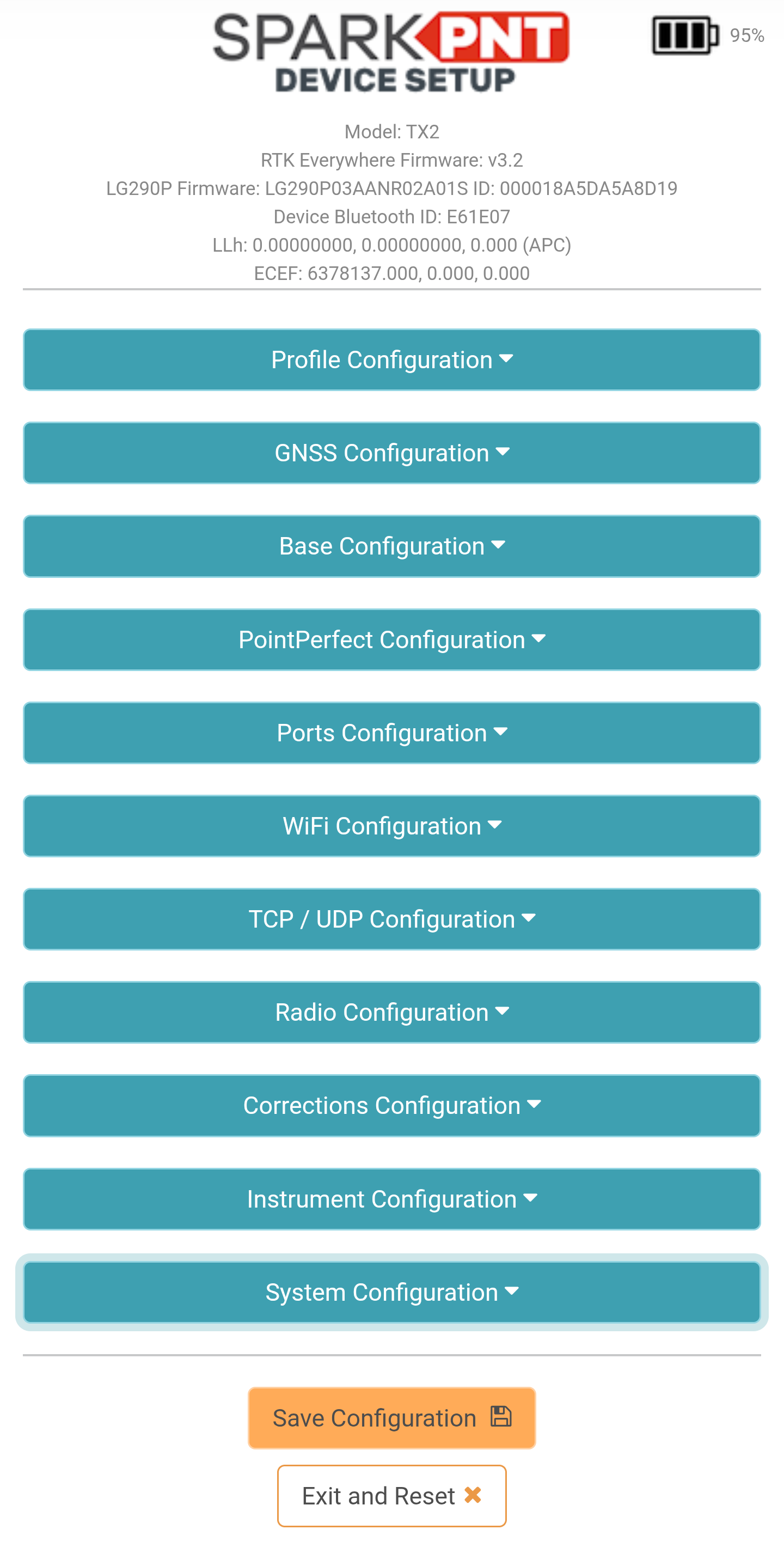
Browser with rtk.localwebpage.
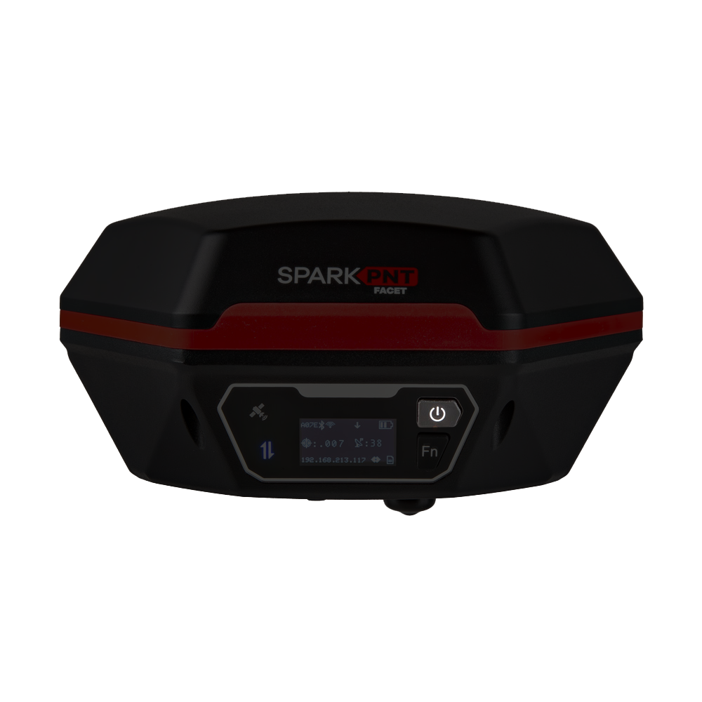
Status Indicators
There are two LED status indicators on the front of the FPM.
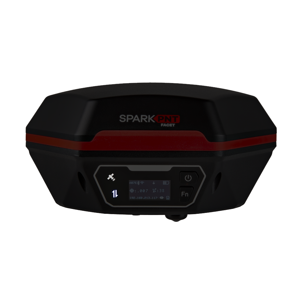
- The GNSS icon () indicates the GNSS solution status.
- A yellow LED will blink once per second when a GNSS fix is achieved.
- A green LED will illuminate solid when RTK Fix is achieved.
- The Connection icon () indicates the WiFi or BLE connection status.
- The LED blinks once per second while waiting for a connection.
- The LED will turn solid, once it is connected to a phone, laptop, WiFi network, etc.
Initial Setup
Users simply need to attach their FPM to a surveying post or mount point using the 5/8"-11 TPI threaded insert on the bottom of the FPM. This kit also includes a 1/4" adapter for additional mounting options.
Orientation and Alignment
For the most accurate positioning, users should align their device as vertically straight as possible. Additionally, the user interface (front of the device) should be facing north as defined by the device's north reference point.
When marking positions, users can also provide the pole height and distance between the ARP and APC in the RTK Everywhere firmware. This will allow users to accurately mark their positions based on the bottom of the surveying pole.
Placement and Surroundings
This section provides general placement considerations for precision GNSS surveying. Below, are some useful examples of ideal locations for surveying.
- Ideal locations
- Open fields
- Hilltops
- Poor locations
- Canyons and valleys
- Cities or dense urban areas
- Dense foilage
Obstructions and Multipath
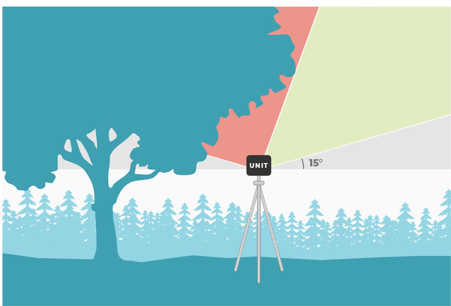
For precision GNSS surveying, the receiver works best with a wide-open, unobstructed view of the sky.
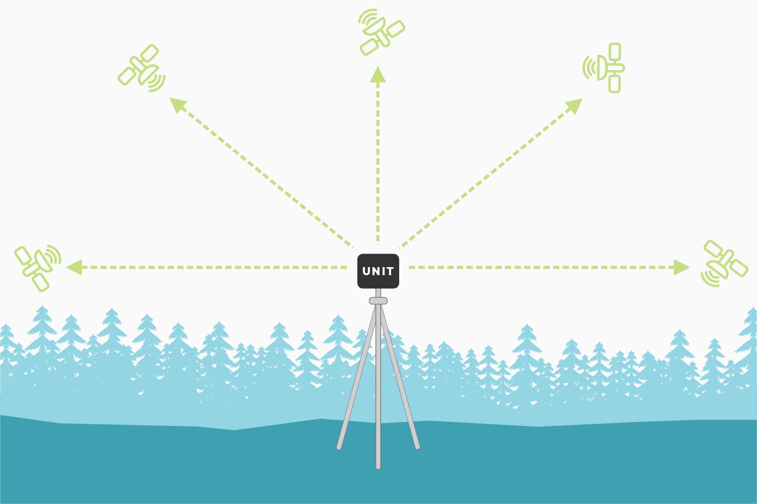
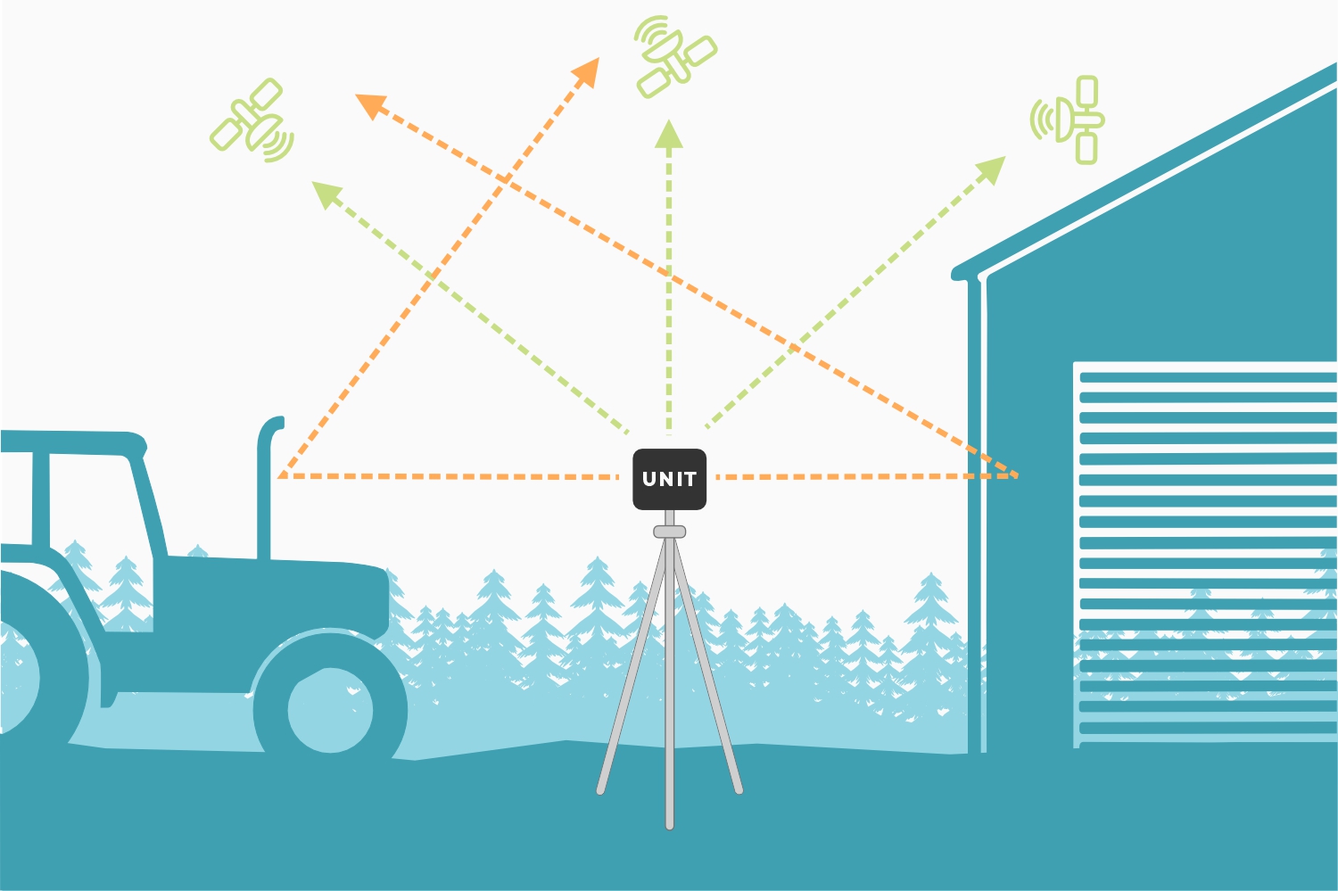
Obstructions can create multiple paths for signals. This introduces timing errors into the solutions provided by the GNSS receiver reducing its precision and accuracy.
By default, the FPM ignores any signals from satellites positioned below, 15° above its horizon (see image). This mitigates any multi-path errors from any obstacles on the horizon; such as buildings, trees, cars, etc.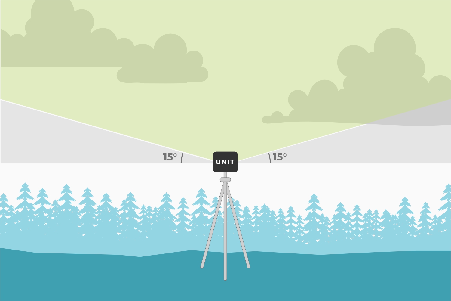
Obstructions can also reduce the performance of the GNSS receiver and the precision of its solutions.
Dilution of Precision
The geometric arrangement of satellites, significantly influences the precision of GNSS solutions. A well-distributed arrangement of satellites allows for more accurate positioning by minimizing errors related to signal distortion and multipath effects. When satellites are positioned at wide angles relative to each other, the geometric dilution of precision improves, enhancing precision of the positioning solutions. Conversely, when satellites cluster closely together in the sky, it can lead to degradation in the geometric dilution of precision and less reliable positioning solutions. Therefore, optimal satellite geometry is crucial for achieving high-precision GNSS solutions.
RF Interference Sources
Nearby electronics can interfere with the reception of the GNSS signals. It is recommended that users limit the use of wireless electronics that produce RF noise. Especially those that operate near the frequencies of GNSS signal bands.
Rover
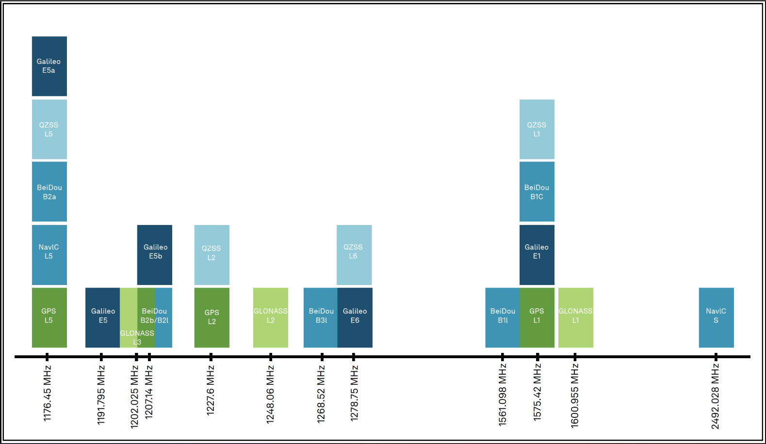
In Rover mode, the FPM will receive L1, L2, and L5 GNSS signals from the four constellations (GPS, GLONASS, Galileo, and BeiDou) and output the devices' position with accuracies around 700mm. The device will calculate the position based on the combination of GNSS and any correction signals (primarily SBAS, if available). Similar to a standard-grade GNSS receiver, the FPM will output industry standard NMEA sentences at 2Hz and can broadcast them to any paired Bluetooth® device. The end user will need to parse the NMEA sentences using commonly available mobile apps, GIS products, or embedded devices (there are many open source libraries).
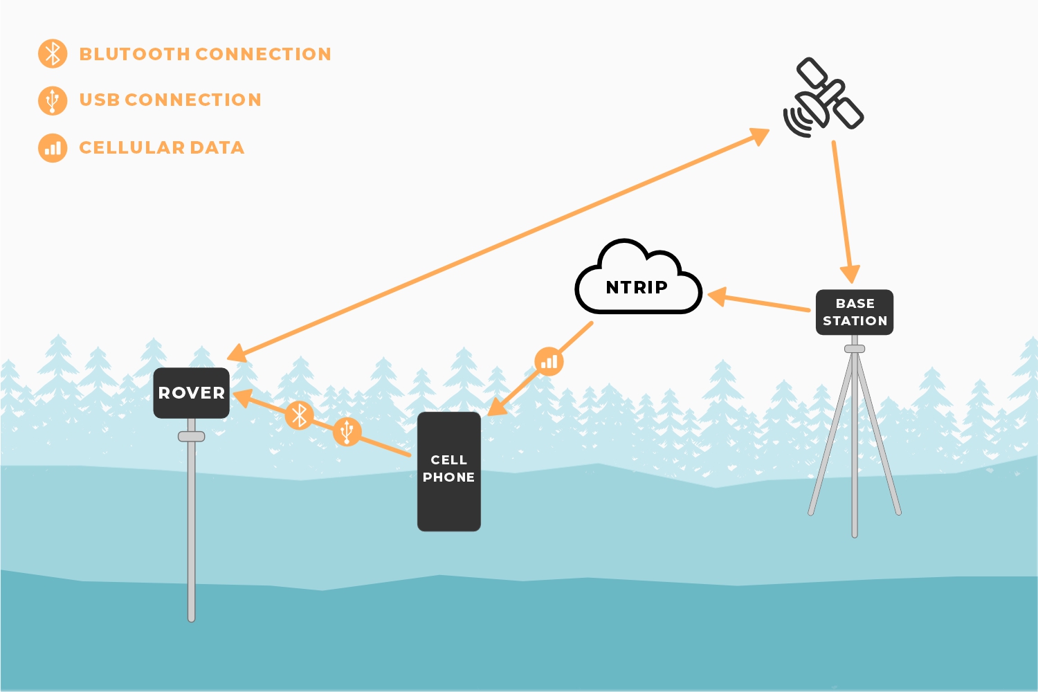
Rover with RTK
In Rover with RTK mode, the FPM will receive GNSS signals and combine them with RTCM correction data to achieve accuracy of approximately 8mm horizontal positional accuracy and 15mm vertical accuracy. The RTCM correction data is most easily obtained over a cellular connection to the Internet using a free app on your phone (see SW Maps or Lefebure NTRIP) and sent over Bluetooth®. Additionally, corrections can be obtained over WiFi, or ESP-NOW. Correction data can come from 2nd unit setup as a base station, from a free local base station, or from a paid service. See the Quick Start guide and the NTRIP Client for more information.
Rover with PPP-RTK
In Rover with PPP-RTK, the FPM will receive GNSS signals and combine them with correction data provided over an IP connection (usually a cell phone hotspot). The corrections are State Space Representation (SSR) based and are also known as PPP-RTK. These corrections are obtained from ublox's PointPerfect network. Time to RTK Fix can take up to 300 seconds and has 14 to 60mm horizontal positional accuracy.
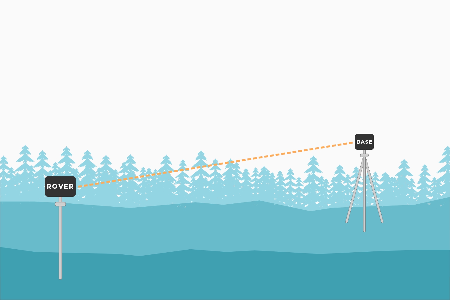
Base Station
In Base Station mode the device is mounted to a fixed position (like a tripod or roof) and will initiate a survey. After 60 to 120 seconds the survey will complete and the FPM will begin transmitting RTCM correction data over the built in 2.4GHz radio (if ESP-NOW is enabled). A base is often used in conjunction with a second FPM unit (or RTK Facet, RTK Surveyor, Express, Express Plus, etc) set to Rover to obtain the 8mm accuracy. Said differently, the Base sits still and sends correction data to the Rover so that the Rover can output a really accurate position. The relative accuracy of this mode is 8mm base-to-rover but has higher (up to a meter) of absolute inaccuracy. See how to set up a permanent base to decrease the absolute inaccuracy.
Base Station with NTRIP
In Base Station with NTRIP the device will enter Base Station mode. If WiFi is available, and the NTRIP Server(s) is enabled, its corrections will be broadcast to up to four NTRIP casters and made available to any rover that also has internet access and is within 10-20km.