Quick Start: USB Setup - CONFIG ESP32
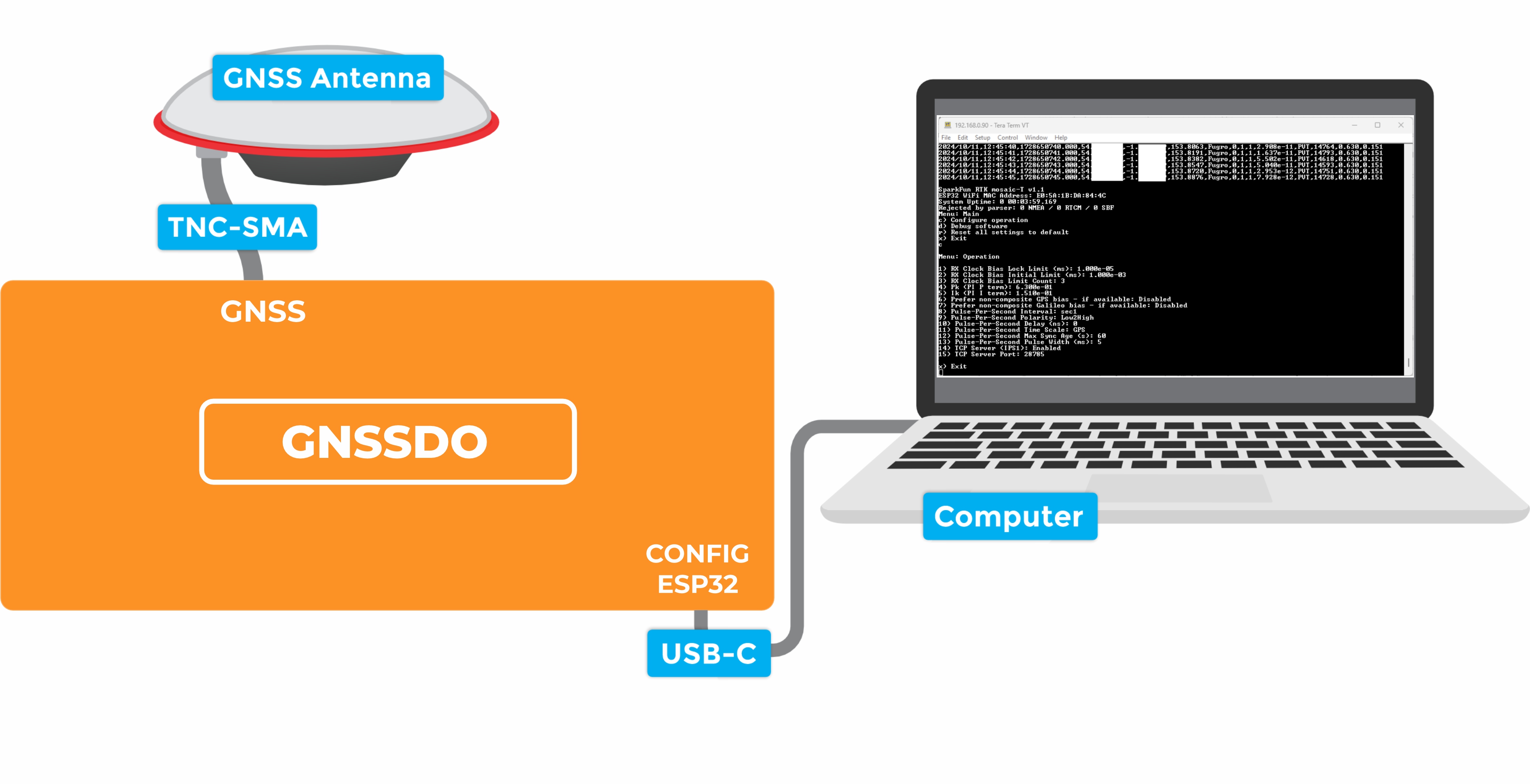
The SparkPNT GNSSDO(+) contains an ESP32-WROVER microcontroller module, which is able to discipline the frequency of the internal temperature-controlled crystal oscillator. By linking the CONFIG ESP32 USB-C port to your computer, you can view and modify the settings of the ESP32 firmware using a terminal emulator.
You can not power the GNSSDO+ from a standard USB (2.0) port. It requires more current than a standard port can deliver.
The GNSSDO+ contains a Power Path priority circuit. From highest to lowest, the Power Path priorities are:
- PoE
- DC-In (Screw Cage Terminal)
CONFIG ESP32USB PortCONFIG MOSAICUSB Port
If you have CONFIG ESP32 connected to a standard USB (2.0) port, you will need to: provide power from PoE or DC-in; or install a power switch in the CONFIG ESP32 cable to disconnect the power and provide Power Delivery power via CONFIG MOSAIC.
1 - Connect the GNSS antenna
- Inside your SparkPNT GNSSDO(+) kit, you will find the L1/L2/L5 GNSS "UFO" antenna. It has a TNC connection. Use the supplied TNC-SMA cable to connect the antenna to the
GNSSSMA connection on the GNSSDO(+). - The antenna needs a clear view of the sky. If you are working indoors, put the antenna outside and pass the cable through a window. (Insulating double-glazed windows have a coating which can block the GNSS signal.)
- Make sure the antenna is securely mounted to a structure so that it cannot be moved.
2 - Download and install a terminal emulator like Tera Term
- To communicate with the firmware running on the ESP32, you will need a serial console or terminal emulator.
- If you are using Windows, we still recommend Tera Term
3 - Connect the GNSSDO(+) to your computer
- Use the supplied USB-C cable to connect the
CONFIG ESP32port to your computer.- You may need to install a USB driver first, so that the CH340 serial interface chip is recognized.
4 - Open the terminal emulator
- Open the terminal emulator and connect to the CH340 COM port. Select 115200bps as the baud rate.
- Once connected, you will see a debug message from the ESP32 every second. The message contains the date, time, Lat, Long and other information about the clock accuracy.
- Pressing any key will open the configuration menu, allowing you to change the firmware settings if needed.
- The firmware settings are stored in flash (non-volatile) memory when you exit the menus. After changing them, exit the menus completely, then you can disconnect the computer and power the GNSS using the supplied wall charger.
You should never need to change most of the firmware settings, the default settings will meet the needs of almost all users.
Enabling the TCP Server (IPS1) option via the Configure Operation menu will allow you to access the firmware serial console via TCP. The firmware settings can then be accessed over the Ethernet or Ethernet-over-USB interfaces, instead of CONFIG ESP32 USB-C. The TCP port number can be changed via the menu; the default TCP port is 28785.
The following sections will help if your GNSSDO(+) is not working as expected:
The red power PWR LED will light up when the GNSSDO(+) has power. If the PWR LED is off, make sure the USB cable is connected. Please see the note above regarding GNSSDO+ Power Path priority.
The OLED display will only show position information (Lat, Long, Alt etc.) once a satellite signal has been acquired. If you see only an IP address on the display, check the SMA to TNC cable is connected correctly and that the antenna is outside with a clear view of the sky. Use a male-female SMA extension cable if needed to increase the cable length.
If you can not see the debug messages and configuration menu in the terminal emulator, check that: you have installed the CH340 driver if needed; you are connected to the CH340 COM port; you have selected 115200bps as the baud rate.