Hardware Assembly
When assembling the SXM-E, users should attach any power connections last. While there shouldn't be any issues with hot-swapping peripherals, it is common practice to power electronics as the last step of the assembly process (and the power should be disconnected before removing components).
What is in the Box?
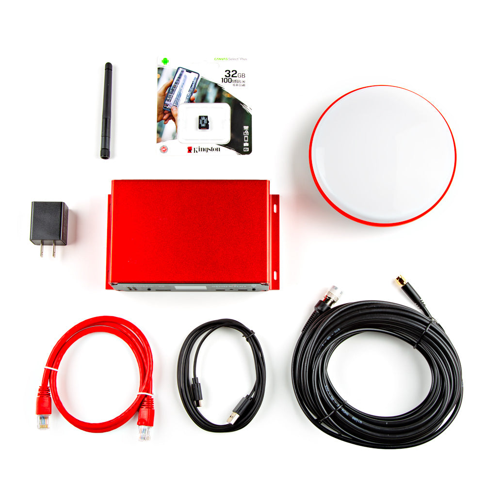
The SparkPNT SXM-E comes packaged as a complete kit, with all the accessories you'd need to set up an RTK base station or NTRIP server. Inside the kit, users will find the SXM-E, GNSS antenna, and another box containing additional accessories. Inside, the accessory box, users will find the CAT-6 Ethernet cable, USB cable, SMA to TNC cable, USB power supply, WiFi antenna, a pack of silicone bumpers, and 32GB SD card.
USB-C Ports
The USB ports are utilized to configure the mosaic-X5 module and ESP32 WiFi settings. Additionally, the USB ports can also be used as a power source for the SXM-E.
The USB port to the mosaic-X5 can be used to configure the module through an IP port, for serial communication to stream the GNSS data, and access the SD card as a mass storage device. To connect to the mosaic-X5, users only need to plug a USB-C cable into the CONFIG MOSAIC USB port and their computer.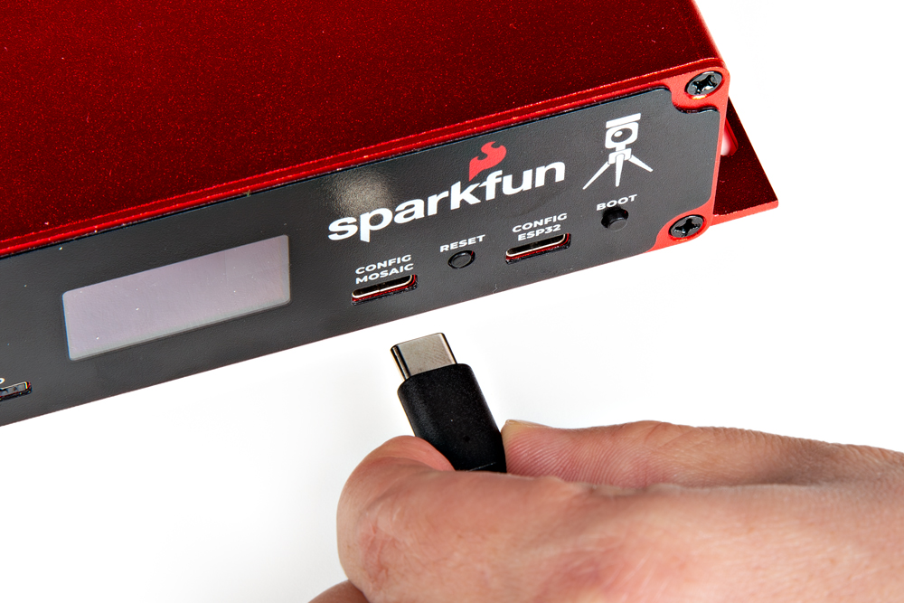
With the default firmware, the USB port for the ESP32 is used for serial communication to configure the network settings of the Ethernet-to-WiFi bridge. To configure the network settings for the ESP32, users only need to plug a USB-C cable into the CONFIG ESP32 USB port and their computer.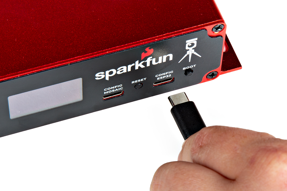
Depending on their computer's operating system, users may need to install USB drivers to interface with the mosaic-X5 and/or the ESP32. Users may also need to install a terminal emulator for serial communication with the mosaic-X5 and the ESP32.
Antennas
This kit includes two separate antennas, a GNSS antenna to receive the GNSS signals and WiFi antenna for remote access.
When selecting antennas and/or cables for the SXM-E, double-check the polarity of the connection.
Your SXM-E is equally at home on your desk, lab bench or in a server rack. But you're still going to want to put the GNSS antenna outdoors, so it will have the best view of the sky. This kit includes a 10m (~33') cable for the GNSS antenna. For longer distances, we recommend using good quality low-loss RG58 SMA extension cables. The GNSS SMA antenna connection is standard polarity. If you want to extend the ESP32 WiFi / BT antenna connection too, you'll need a Reverse Polarity (RP) cable for that.
SMA Female to SMA Male Cable (10m, RG58)
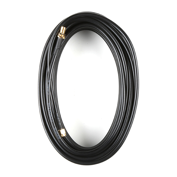
Use this extension cable for the GNSS antenna. This cable will not work with the WiFi/BLE antenna due to the polarity of the connectors.
RP-SMA Male to RP-SMA Female Cable (10M, RG58)
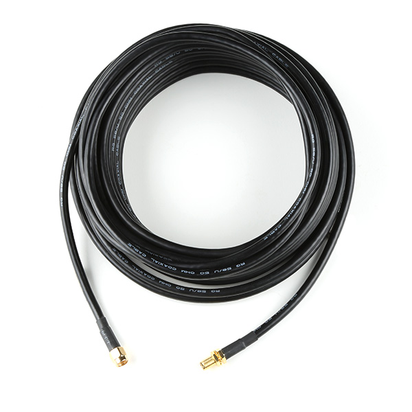
Use this extension cable for the WiFi/BLE antenna. This cable will not work with the GNSS antenna due to the polarity of the connectors.
GNSS Antenna
In order to receive GNSS signals, users will need a compatible antenna. With the parts included in this kit, connect the L1/L2/L5 (tri-band) GNSS antenna to the SXM-E using the TNC-to-SMA cable.
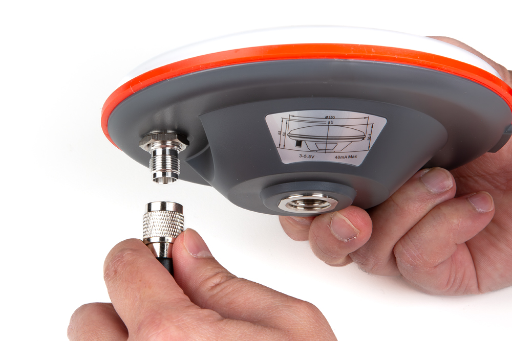
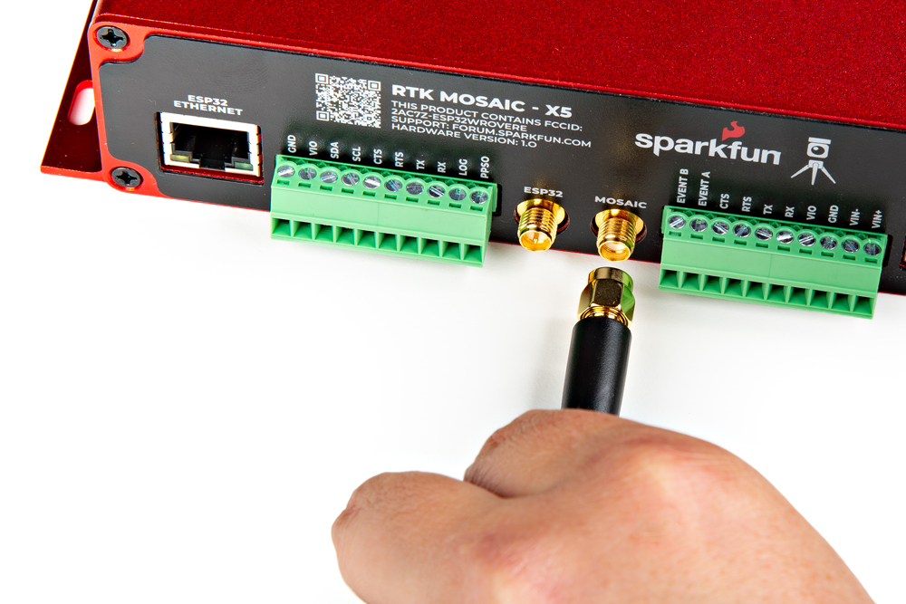
Users should mount their GNSS antenna outside, where it will have a clear, unobstructed view of the sky. Avoid areas with nearby buildings, EMF structures (i.e. radio towers or power lines), and vegetation (i.e. trees). These objects can increase errors due to signal muti-path, interference, and elevated noise plane.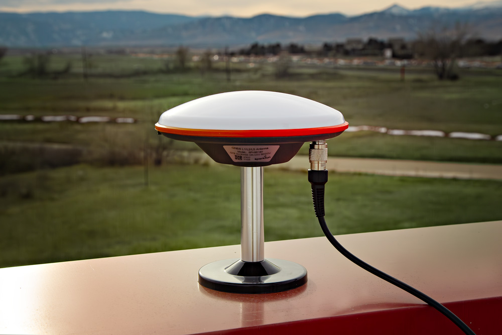
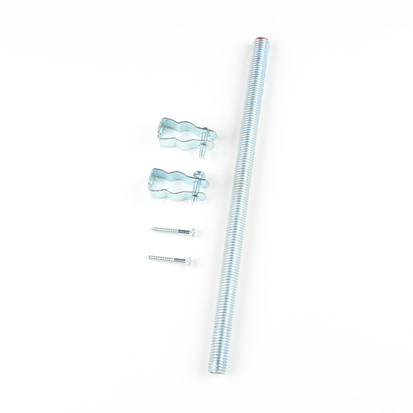
This kit does not include any mounting hardware for the antenna. To permanently mount the antenna outside, we recommend the following products:
GNSS Antenna Mounting Hardware Kit
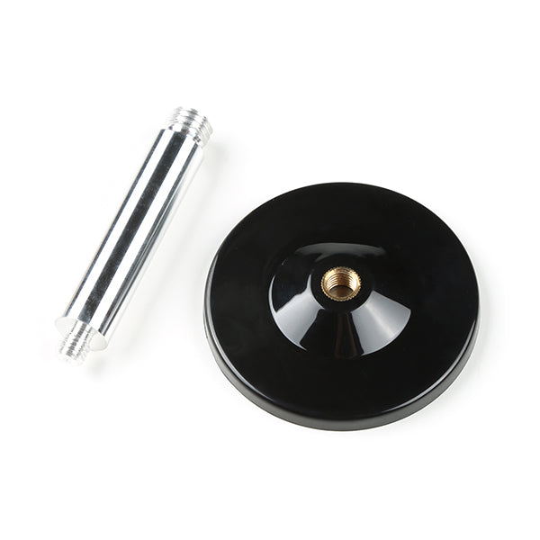
GNSS Magnetic Antenna Mount
WiFi Antenna
For the WiFi connection, users will need a compatible antenna. Connect the WiFi antenna, included in this kit, to the SXM-E.
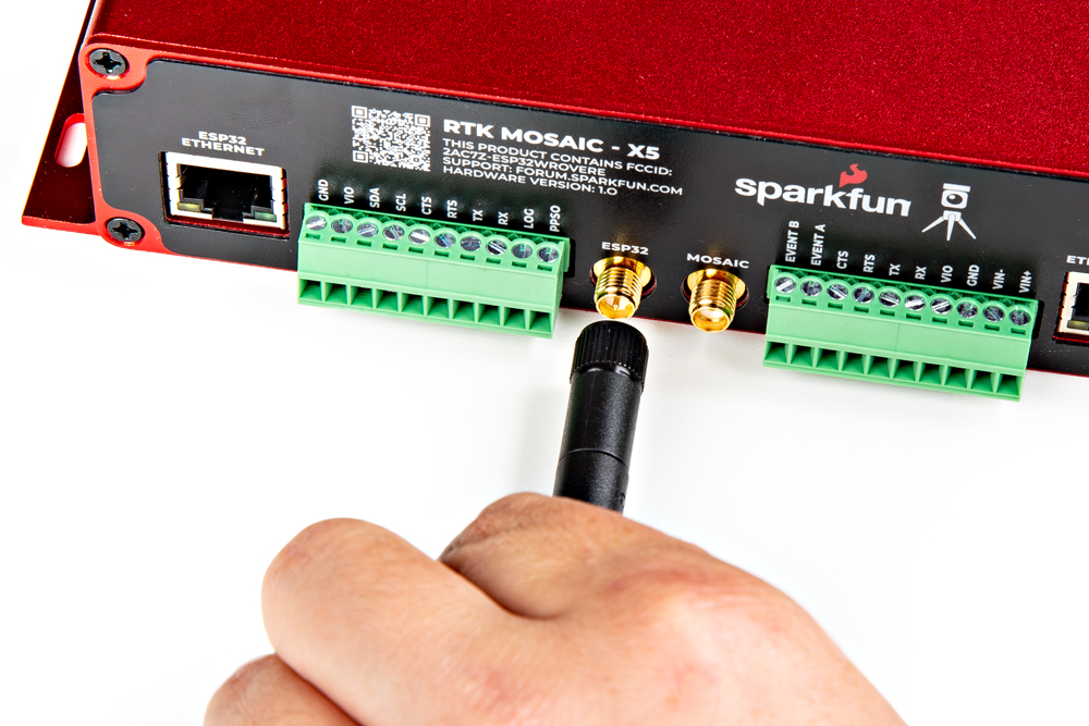
The ESP32 is only compatible with 2.4GHz bands and cannot access the 5GHz band.
The ESP32 firmware we provide is only compatible with basic SSID and Password WiFi authentication.
- The firmware is not compatible with networks that implement other provisioning methods such as a captive portal, a QR code, or Wi-Fi protected setup.
Ethernet Jacks
There are two ethernet jacks on the SXM-E, which can be used to provide network access to the mosaic-X5 module. In addition, one of the ethernet jacks supports power over ethernet (PoE) to power the device.
- LAN Cable
- Wireless LAN
The jack to the mosaic-X5 allows users to provide internet access and power; it supports PoE. To provide network access, users should connect the SXM-E from the MOSAIC ETHERNET (PoE) jack to their local area network with the (CAT-6) ethernet cable provided in the kit.
- To power the device, a PoE network switch or PoE injector should be installed in between the network connection to the SXM-E.
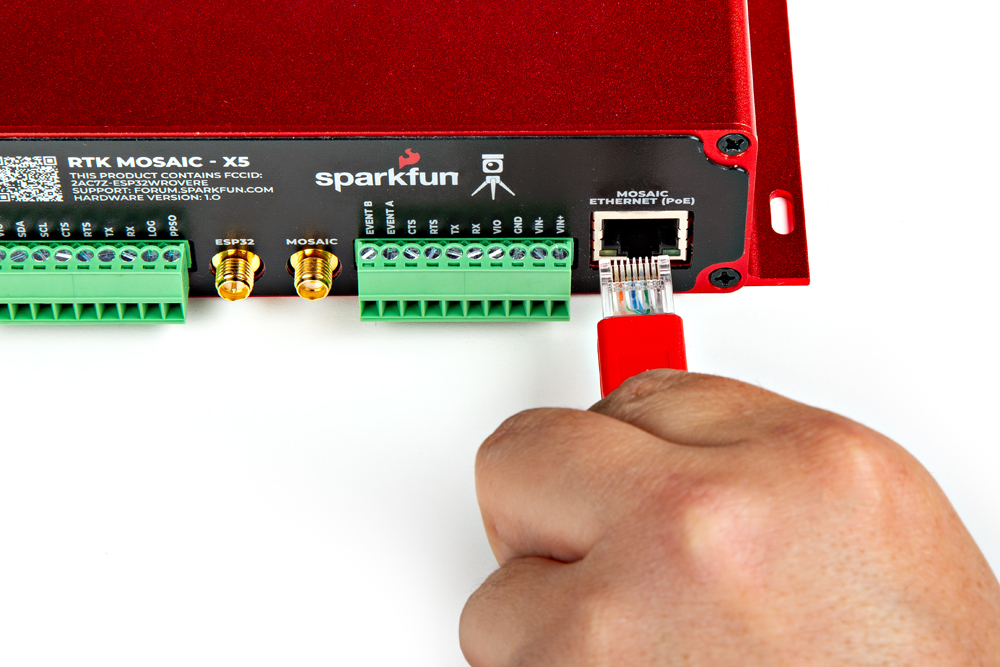
MOSAIC ETHERNET (PoE) jack.
The jack to the ESP32 allows users to provide WiFi access to the mosaic-X5, by utilizing the ESP32 as a WiFi network bridge.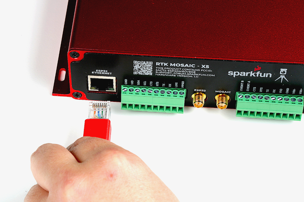
ESP32 ETHERNET jack.
To set up the WiFi bridge, connect the provided (CAT-6) ethernet cable between the MOSAIC ETHERNET (PoE) and ESP32 ETHERNET jacks on the SXM-E.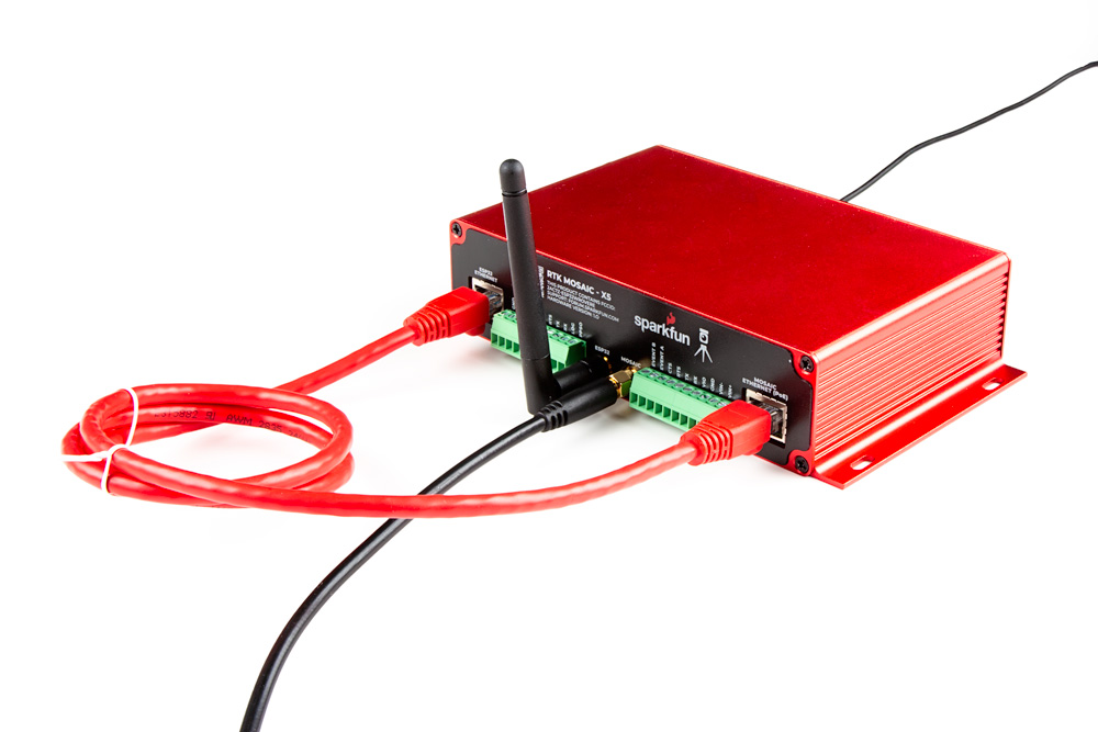
MOSAIC ETHERNET (PoE) and ESP32 ETHERNET jacks.
Users will need to configure the WiFi connection for the ESP32, through the CONFIG ESP32 USB-C port.
Users should avoid wrapping the ethernet cable around the WiFi antenna; doing so will result in the loss of data packets and cause the web page to freeze. If users must coil the wiring, we recommend that the coil be placed at least 2-3" away from the WiFi antenna.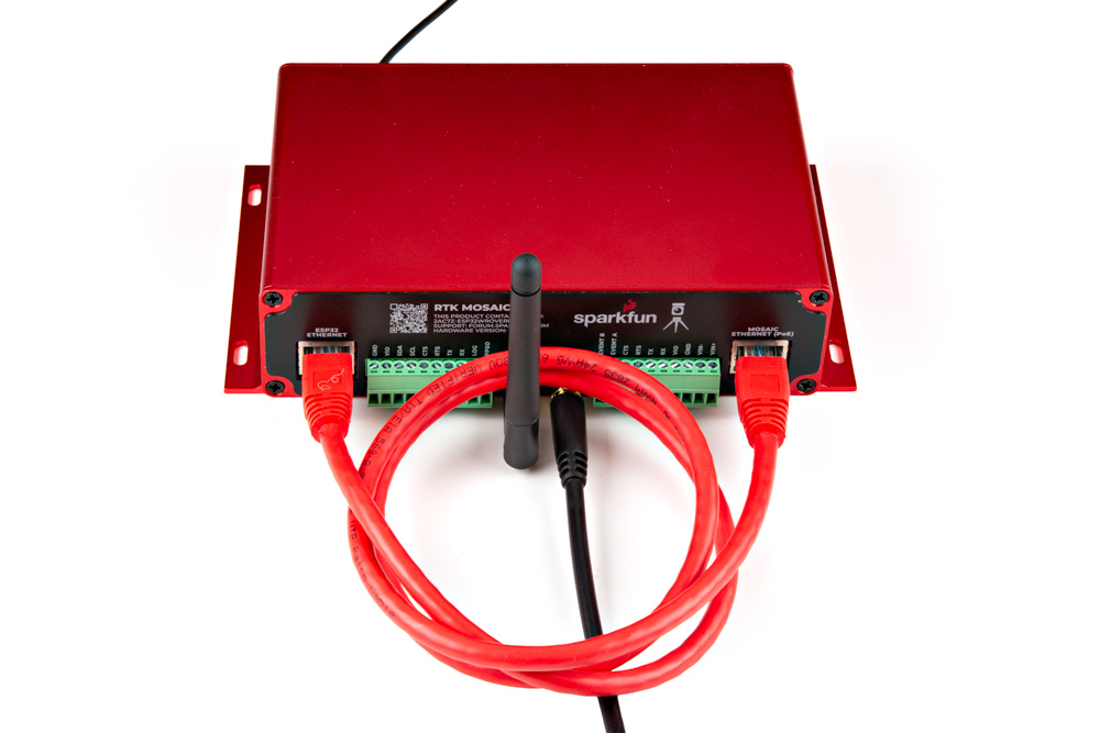
Users can configure the mosaic-X5 module through the network connection (i.e. ethernet or WiFi).
SD Card Slot
An µSD card slot is available for users to log and store data, locally on the board. Users will need to insert a compatible SD card and configure the mosaic-X5 module for data logging.
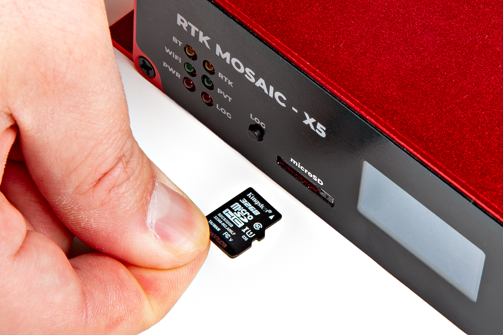
The mosaic-X5 supports µSD cards with a FAT32 file system (i.e. only cards up to 32GB in size).
Before logging can take place, it is necessary to define a "logging stream" using the Logging page or RxTools. Streams can contain NMEA or SBF (Septentrio Binary Format) data; SBF can contain RTCM and/or RINEX.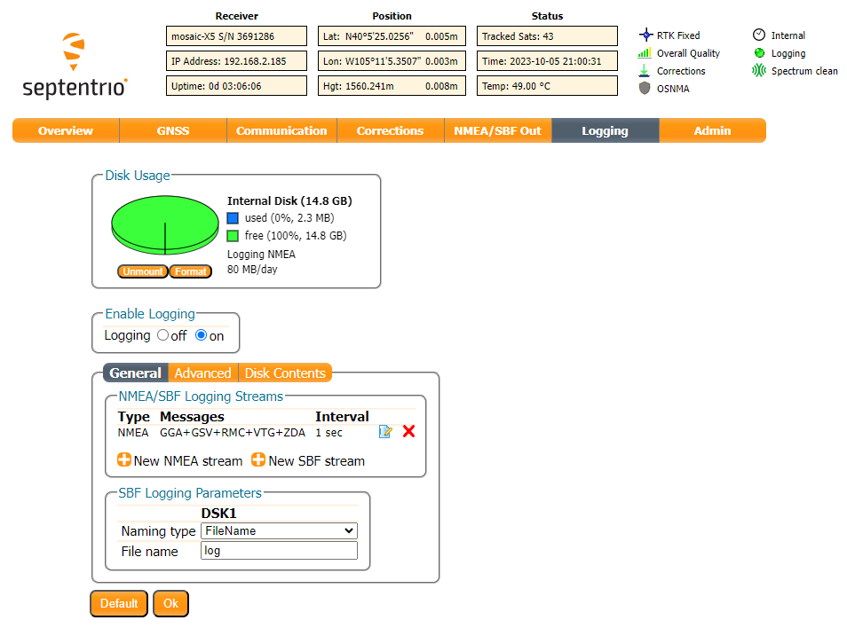
There are multiple ways to configure and enable data logging to an SD card. However, the simplest method is with the LOG button. Once the stream is defined,
- Pressing the LOG button (< 5s) toggles data logging to the SD card on and off.
- Holding the LOG button for more than 5 seconds (> 5s) and then releasing it, will force the board to:
- Unmount the SD card if it was mounted
- Mount the SD card if it was unmounted
For more information, please reference the SD Card Slot section.
IO Terminals
Users can easily attach accessories to the SXM-E by wiring them into the pluggable screw terminal blocks on the back of the enclosure.
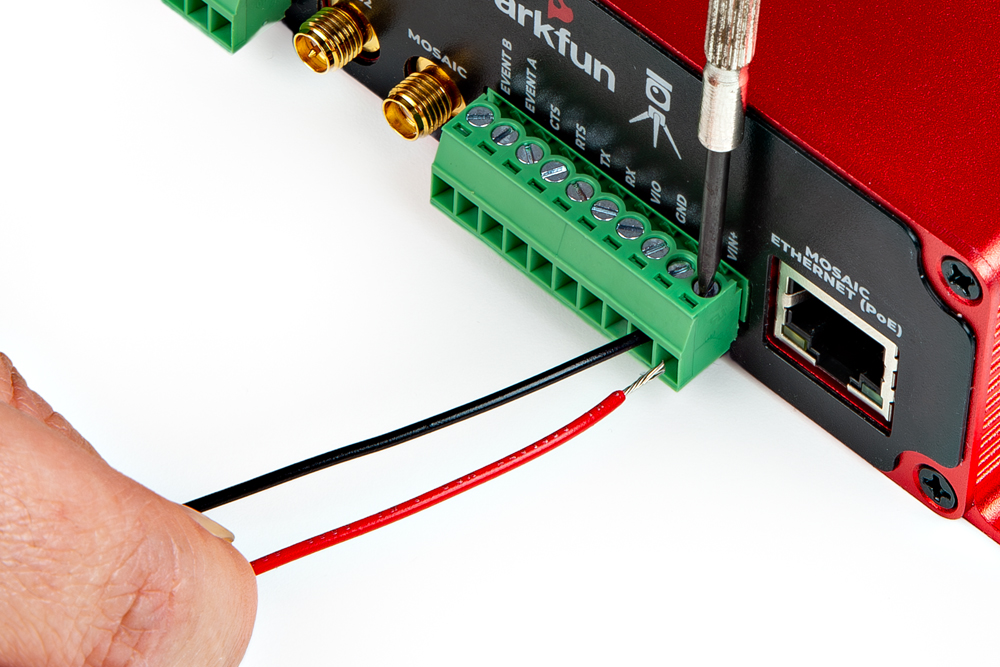
For multiple connections or wiring harnesses, users can disconnect the pluggable terminal blocks from their sockets on the SXM-E.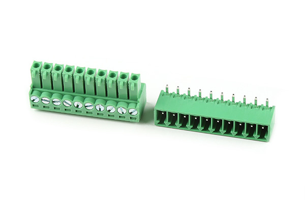
Users can wiggle or use a soft/rigid object to carefully pry the pluggable terminal block off from its connector. In the picture below, a plastic name tag (~1.5mm thick) is used to carefully pry the terminal block up. We have also found the edge of a PCB ruler works great too.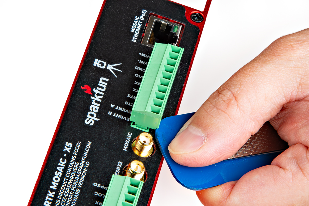
Once wired up, users can simply push the pluggable terminal block back into its socket.
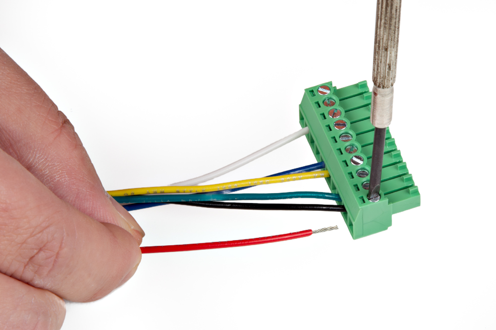
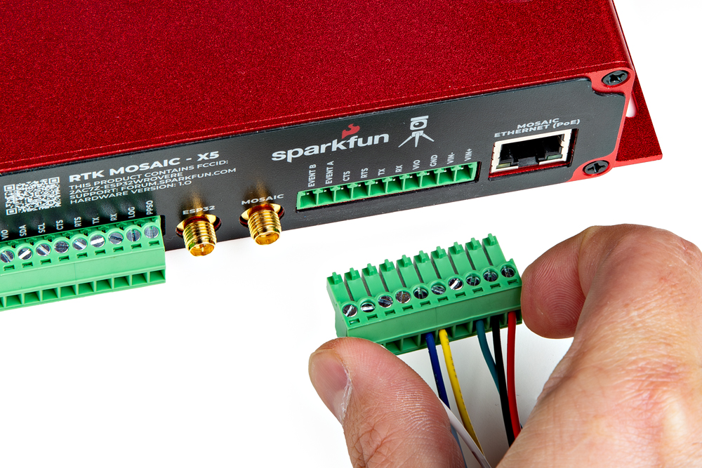
To avoid shorts or damaging the SXM-E, verify the wiring with the labels on the back of the enclosure.
Radio Transceivers
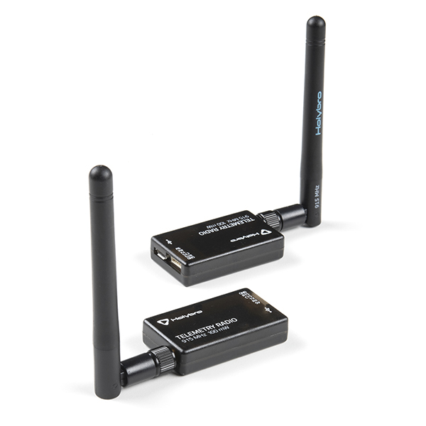
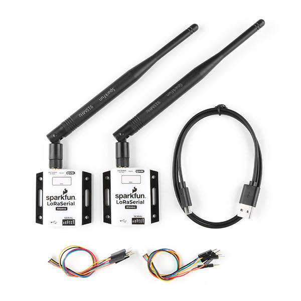
Users can also utilize the terminal blocks to interface with one of our radio transceivers for RTK correction data. We recommend utilizing our breadboard cable to connect those radios to the SXM-E.
SiK Telemetry Radio V3 - 915MHz, 100mW
WRL-19032
SparkFun LoRaSerial Kit - 915MHz (Enclosed)
WRL-20029
Breadboard to JST-GHR-06V Cable - 6-Pin x 1.25mm Pitch (For LoRaSerial)
CAB-23353
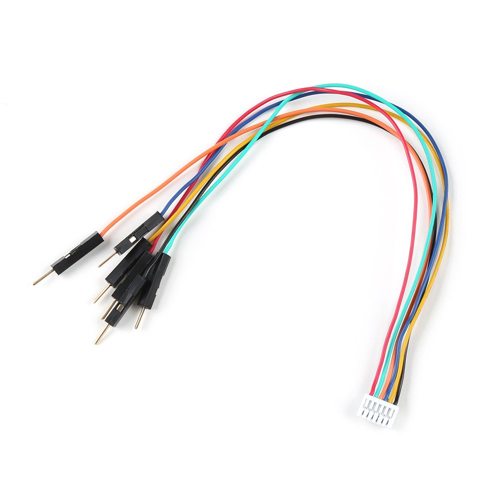
When connecting the SXM-E to one of our radio transceivers, users need to be aware of the pin connections between the products. Although the labels on each device may vary, their pins will function the same (except for the power input/output pins).
Please remember that the power output (VIO) is preset to 3.3V by default. When utilizing the SiK telemetry radios, users will need to open the enclosure and move the VIO switch.
- Radio Pins
- Terminal Block
Below is a diagram of the pin connections for the 6-pin JST GH connector on the radios, which should be also labeled on their enclosure.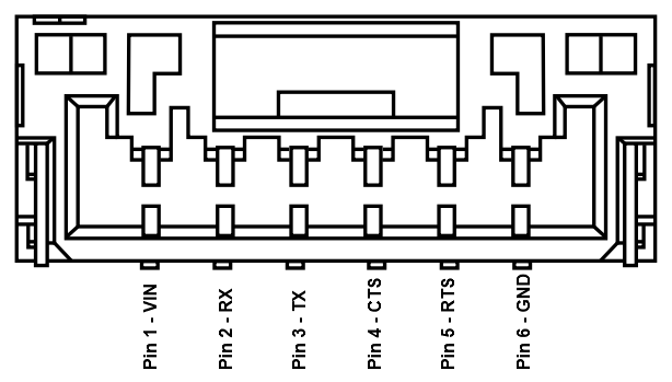
| Label | 5V | RX/RXI | TX/TXO | CTS | RTS | GND |
|---|---|---|---|---|---|---|
| Function | Voltage Input
| UART - Receive | UART - Transmit | Flow Control | Flow Control | Ground |
Below are the UART pin connections to the mosaic-X5 GNSS receiver, which are labeled for the pluggable terminal blocks on the SXM-E enclosure.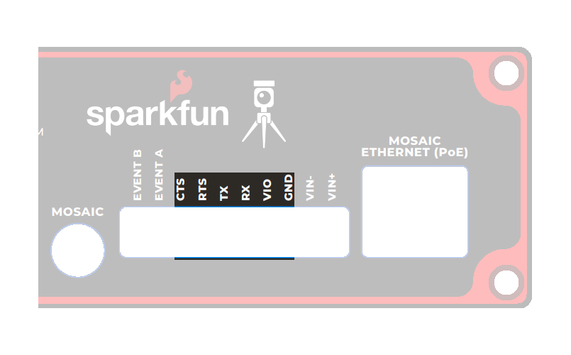
| Label | VIO | RX | TX | CTS | RTS | GND |
|---|---|---|---|---|---|---|
| Function | Voltage Output
| UART - Receive | UART - Transmit | Flow Control | Flow Control | Ground |
When connecting the SXM-E to either of the radios, the wiring connections should follow the table below. If the flow control is not enabled, then only the RX, TX, and GND pins are utilized. As an example, the wiring between a host system (i.e. SXM-E) and the LoRaSerial Kit radio is shown in the image below; as documented in the LoRaSerial product manual.
| SXM-E | RX | TX | RTS | CTS | GND |
|---|---|---|---|---|---|
| Radio | TX | RX | CTS | RTS | GND |
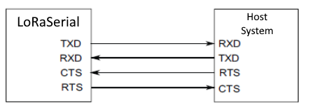
Source: LoRaSerial product manual
By default, the radios in the LoRaSerial Kit - 915MHz are pre-configured for point-to-point communication and a paired with each other. For instructions on other configurations, please reference the product manual for the LoRaSerial Kit.
Outdoor Enclosure
The SXM-E comes in a beautiful custom extruded aluminum enclosure, with machined end panels and matching stickers. The slotted flanges make it easy to install and secure the enclosure in many locations. But the enclosure only provides limited protection against the ingress of dust and water; it is IP42.
If you want to permanently install it outside, you'll need a suitable weatherproof box. We recommend the Orbit 57095 - also available from Amazon - back when we put together our very first DIY GNSS Reference Station.
How to Build a DIY GNSS Reference Station
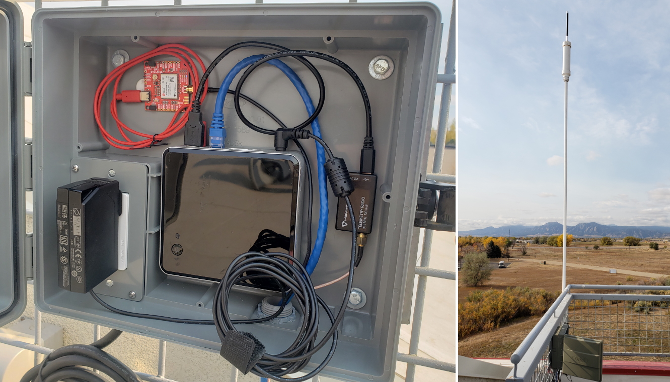
Check out our guide on how to create your own GNSS reference station.
The Orbit enclosure comes with a built-in power outlet, but you don't need it! The SXM-E can be powered by Power-over-Ethernet (PoE), meaning all you really need to run up to the roof is a standard 8-core CAT-6 Ethernet cable. Choose a PoE Ethernet Switch that meets your needs. We have had good experiences with the TP-Link TL-SG1005P - available from many retailers including Amazon.
Enclosure Disassembly
Due to the ESD sensitivity of the mosaic-X5 module, we don't recommend disassembling the SXM-E. However, if users must access the PCB to troubleshoot an issue, make a modification, or repair a component, we highly recommend that they take the necessary ESD precautions to avoid damaging the mosaic-X5 module.
The mosaic-X5 module is sensitive to ESD. Use a proper grounding system to make sure that the working surface and the components are at the same electric potential.
As recommended by the manufacturer, we highly encourage users to take the necessary precautions to avoid damaging their module.
- The PCB is not grounded through the enclosure.
- The PCB features ESD protection on the USB-C connectors and ethernet jacks.
- The mosaic-X5 module also has ESD protection from the
ANT_1antenna input.
iFixit Anti-Static Wrist Strap

Before disassembling the enclosure, users should disconnect the power and all cables from the SXM-E. This will prevent users from creating any shorts and facilitate the teardown process further on.
The internal PCB is only held in place by the front and rear panels of the enclosure. While users can remove the panels first, we recommend that users disconnect the pluggable screw terminal blocks first. Users may find it more difficult to separate the pluggable terminal block from the PCB later in the disassembly process.
-
Users may find it easiest to disconnect the pluggable terminal blocks first; as opposed to later in the teardown process. Users can wiggle or use a soft/rigid object to carefully pry the terminal block off.
Carefully pry the pluggable terminal blocks off. tipIn the picture above, a plastic name tag (~1.5mm thick) is used to carefully pry the terminal block up. We have also found the edge of a PCB ruler works great too.
-
Once the pluggable terminal blocks have been removed, users can remove the front and rear panels of the enclosure. They are held in place with four, M3, Phillips head screws on the corners of each panel.
tipWe recommend removing the front panel first to prevent the Qwiic cable from being yanked off the OLED display or main PCB. Once the front panel is free, carefully lift the panel from the enclosure and disconnect the Qwiic cable from the top connector on the OLED display.
-
At this point, if users have previously disconnected all the cables and the pluggable terminal blocks from the back, the SXM-E PCB should slide out of the enclosure. Users can then, remove the rear panel from the enclosure to complete the teardown process.
To re-assemble the SXM-E, simply reverse the process above.