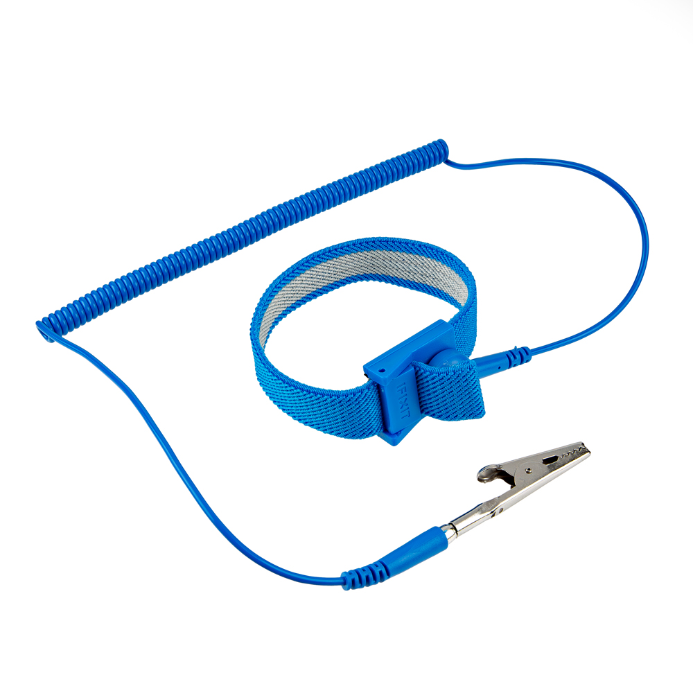
The mosaic-X5 module is sensitive to ESD. Use a proper grounding system to make sure that the working surface and the components are at the same electric potential.
As recommended by the manufacturer, we highly encourage users to take the necessary precautions to avoid damaging their module.
- The PCB is not grounded through the enclosure.
- The PCB features ESD protection on the USB-C connectors and ethernet jacks.
- The mosaic-X5 module also has ESD protection from the
ANT_1antenna input.
iFixit Anti-Static Wrist Strap
We have intentionally kept the ESP32 firmware as simple as possible - supporting only two modes: Ethernet (Mode: 1) and WiFi (Mode: 2). The intention is that you can easily develop your own firmware for the SXM-E using the Espressif ESP IDF if the SparkFun firmware does not meet your needs.
You can of course modify the hardware too, should you want to. The design is completely open-source.
- The ESP32 firmware we provide is only compatible with basic
SSIDandPasswordWiFi authentication. - The firmware is not compatible with networks that implement other provisioning methods such as a captive portal, a QR code, or Wi-Fi protected setup.
Hardware Overview
In this section, we walk you through the hardware design, interfaces, I/O connections, power options and more.
The SXM-E is inspired by the Septentrio mowi (mosaic wireless) open-source design. The SparkFun design builds upon mowi, adding: separate Ethernet ports with mag jacks and Power-over-Ethernet; robust I/O headers with screw cage connections and configurable I/O voltage (3.3V or 5V); µSD data storage; and an OLED display.
Power
The mosaic-X5 and the ESP32 both required 3.3V power. To simplify the power circuitry, the four power sources are combined into a common 5V rail which then feeds individual 3.3V 1A regulators for the mosaic-X5 and the ESP32.
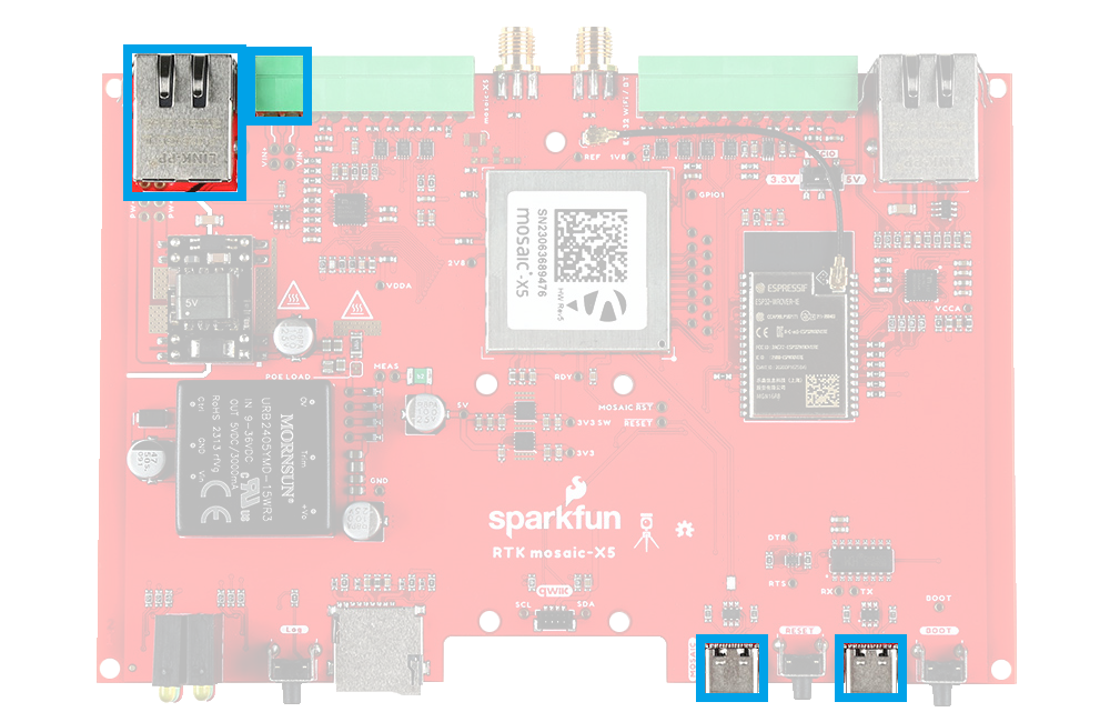
The SXM-E can be powered individually or in combination, with any of the following:
- USB Ports - 5V; delivered via the
MOSAIC CONFIGand/orESP32 CONFIGUSB-C connectors. - Power-over-Ethernet (PoE) - Range: 36 to 57V; delivered via the
MOSAIC ETHERNETRJ45 MagJack connector. - External DC Power - Range: 9 to 36V; delivered via the
VIN+andVIN-screw cage terminals.
If you want to measure the board's current draw, you can open the MEAS jumper and measure the current via a pair of breakout pads (see the Jumpers section).
Diodes are used to combine and protect the power sources from each other. Also, a 2A resettable fuse (green) provides additional protection.
For more details, users can reference the schematic and the datasheets of the individual components on the board.
- USB-C Connectors
- Power-over-Ethernet (PoE)
- External DC Power
The mosaic-X5 and ESP32 both have USB-C connections. These USB ports can be used to power the SXM-E during the initial configuration when the mosaic-X5 or ESP32 are connected to a computer.
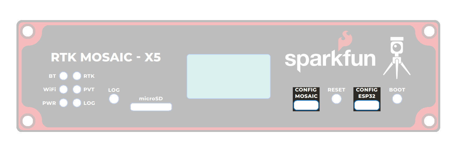
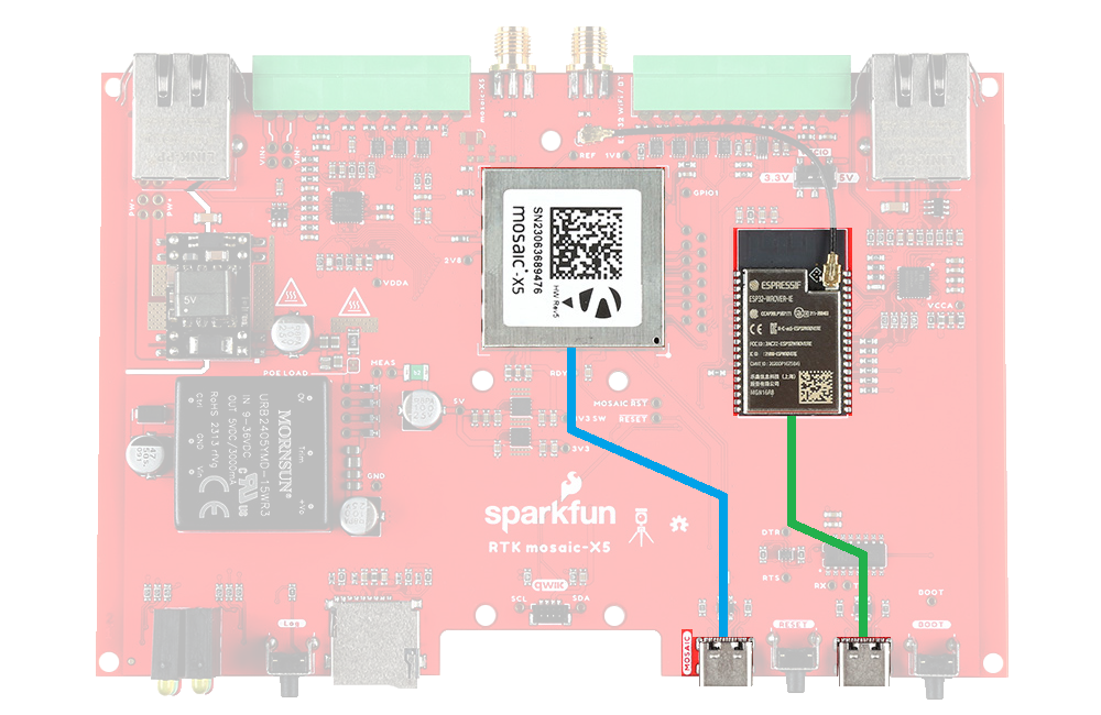
The CH340 allows the ESP32-WROVER to communicate with a computer/host device through the USB-C connection. This allows the ESP32 to show up as a device on the serial (or COM) port of the computer. Users will need to install the latest drivers for the computer to recognize the CH340 (see USB Driver section).
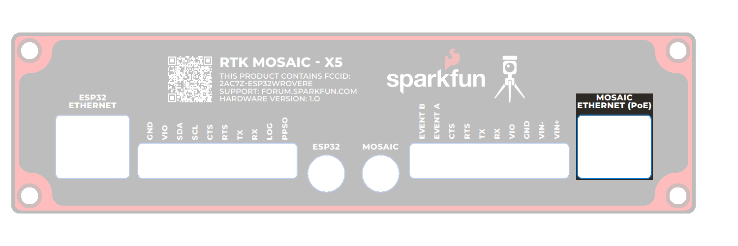
The mosaic-X5 Ethernet port supports Power-over-Ethernet (PoE), allowing the SXM-E to be powered by the network. This is very useful when the SXM-E is mounted remotely - perhaps in a weatherproof box up on the roof. Data and power can be delivered through a single cable, avoiding the need for a separate power connection.
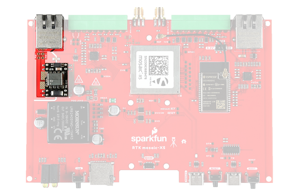
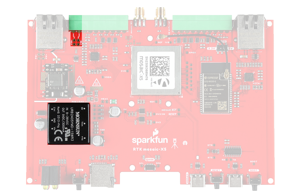
The SXM-E includes a fully-isolated DC-DC converter, for applications where you may want to power the unit from a vehicle. The DC-DC converter accepts DC voltages between 9V and 36V, regulating this down to 5V. The converter is fully isolated to 1.5kV and operates with ~90% efficiency.
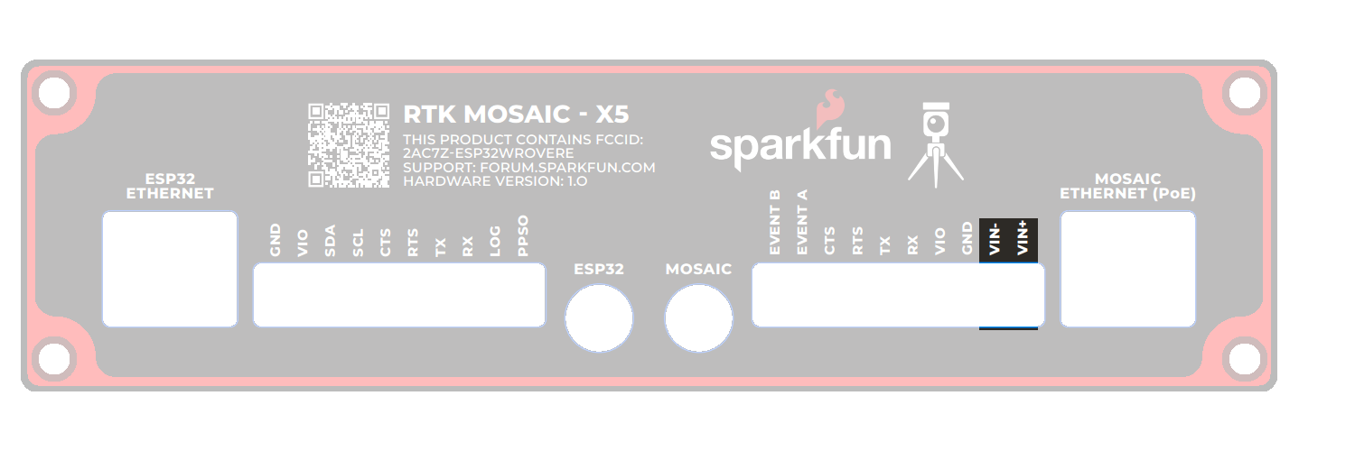
VIN+ and VIN- screw terminal pins for the external DC power input.
For 12V or 24V vehicle power:
- Connect 12V or 24V to the
VIN+screw cage terminal - Connect 0V (chassis) to the
VIN-screw cage terminal
Additionally, make sure that the power source from the vehicle is not directly tied to the vehicle's battery, Always On, or accessory circuits. Otherwise, users will risk killing the battery while the engine is off.
We recommend locating the ignition on or switched power circuit, which is only powered when the key is in the On position and the engine is running.
The On position, is where a key normally rests after the engine is started. However, users can still move the key from the Off position and into the On position without starting the engine. In this case, the alternator is not running and keeping the battery charged.
Modern eco-efficient vehicles may automatically shut down the engine if the vehicle is idling too long. Therefore, cutting off the vehicle's alternator that keeps the battery charged. Luckily, most vehicles with this automatic start/stop technology will monitor the battery's voltage and restart the engine when required. With this in mind, users may want to initially monitor their battery voltage, in case their vehicle isn't "so smart" 😅.
If desired, users can link VIN- to the adjacent GND screw cage terminal. However, this will bypass the voltage isolation and could introduce an unwanted ground loop, particularly if the GNSS antenna ground (shield, 0V) is also connected to the chassis.
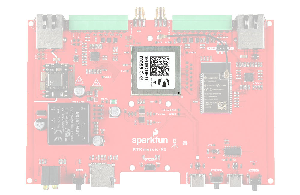
mosaic-X5
The heart of our product is of course the mosaic-X5 GNSS module from Septentrio. It is a very sophisticated chip with multiple interfaces: UARTS, USB and Ethernet. The COM2 and COM3 UART pins, plus GPIO1 and GPIO2, are available as 0.1" test points should you need access to them.
ESP32-WROVER
The only interface the mosaic-X5 doesn't offer is WiFi and that's why we've included an Espressif ESP32-WROVER processor (16MB flash, 8MB PSRAM) with its own Ethernet connection. You can connect the mosaic-X5 directly to your Ethernet network - our product supports Power-over-Ethernet too. Or you can link the mosaic-X5 Ethernet port to the ESP32 Ethernet port and have the ESP32 provide WiFi connectivity. In that mode, the ESP32 becomes an Ethernet to WiFi Bridge, seamlessly passing WiFi traffic to and from the mosaic-X5 via Ethernet.
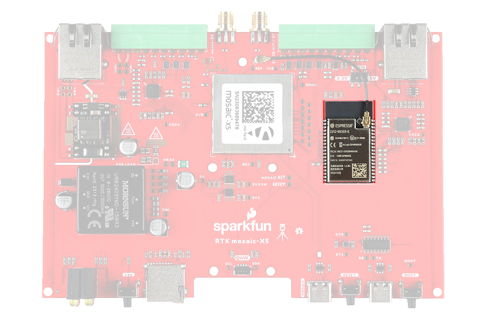
Think of the ESP32 as a co-processor, or riding shotgun... The mosaic-X5 COM4 UART is linked to the ESP32, allowing the two to communicate directly without needing the Ethernet link. In our firmware, the ESP32 requests NMEA GGA data over this link and then displays it on the I2C OLED display.
The ESP32 is only compatible with 2.4GHz bands and cannot access the 5GHz band.
We have intentionally kept the ESP32 firmware as simple as possible - supporting only two modes: Ethernet (Mode: 1) and WiFi (Mode: 2). The intention is that you can easily develop your own firmware for the SXM-E using the Espressif ESP IDF if the SparkFun firmware does not meet your needs.
You can of course modify the hardware too, should you want to. The design is completely open-source.
- The ESP32 firmware we provide is only compatible with basic
SSIDandPasswordWiFi authentication. - The firmware is not compatible with networks that implement other provisioning methods such as a captive portal, a QR code, or Wi-Fi protected setup.
Ethernet PHY Interfaces
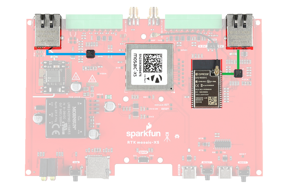
The mosaic-X5 and ESP32 have identical KSZ8041NLI Ethernet PHY interfaces, both connected using Reduced Media-Independent Interfaces (RMII). These allow the mosaic-X5 and ESP32 to be linked directly to your Ethernet network or router, or to each other when the ESP32 is acting as an Ethernet-to-WiFi Bridge.
USB-C Connectors
The mosaic-X5 and ESP32 both have USB-C connections. The MOSAIC USB port is high-speed and connected to the X5 through a balancing transformer. The ESP32 USB port is connected through a CH340 USB-UART IC.
The SXM-E can draw power from either or both USB ports, in addition to Power-over-Ethernet and the DC-DC external input described above.
The CH340 allows the ESP32-WROVER to communicate with a computer/host device through the USB-C connection. This allows the ESP32 to show up as a device on the serial (or COM) port of the computer. Users will need to install the latest drivers for the computer to recognize the CH340 (see USB Driver section).
µSD Socket
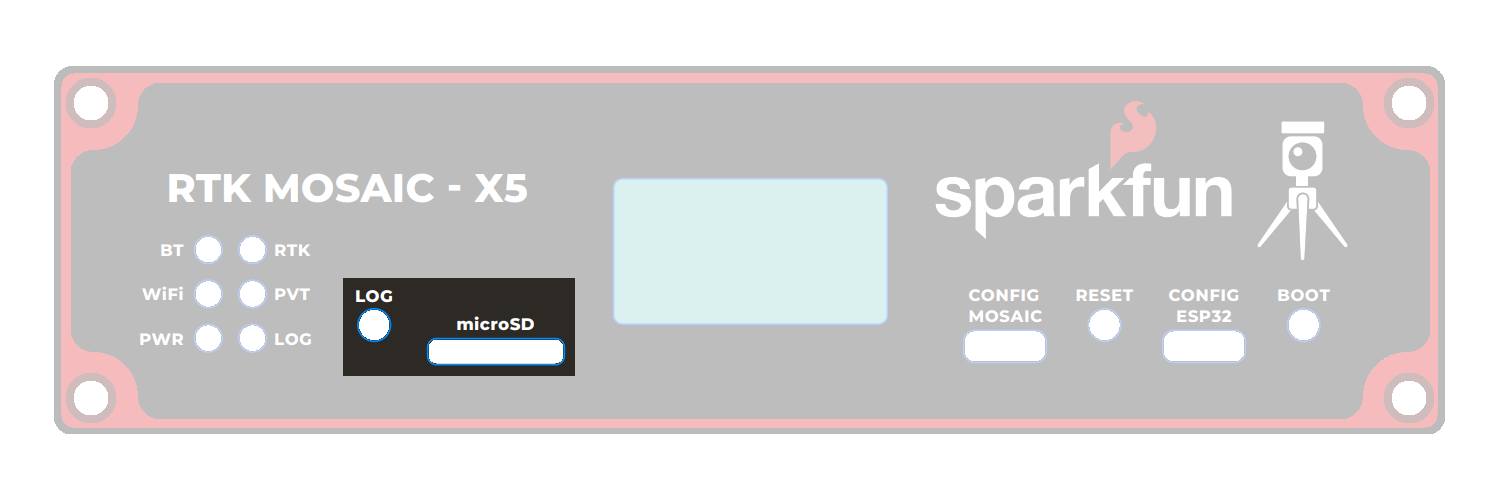
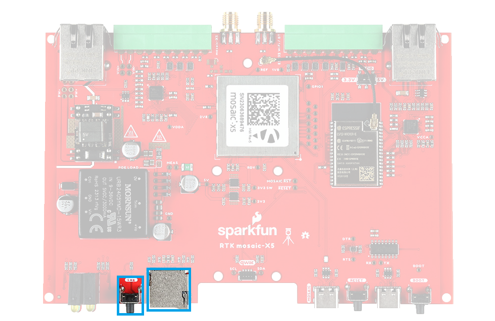
The µSD socket is connected directly to the mosaic-X5 via a one-bit SDIO interface for fast data logging. The mosaic-X5 supports µSD cards with a FAT32 file system (i.e. only cards up to 32GB in size).
Before logging can take place, it is necessary to define a "logging stream" using the Logging page or RxTools. Streams can contain NMEA or SBF (Septentrio Binary Format) data; SBF can contain RTCM and/or RINEX.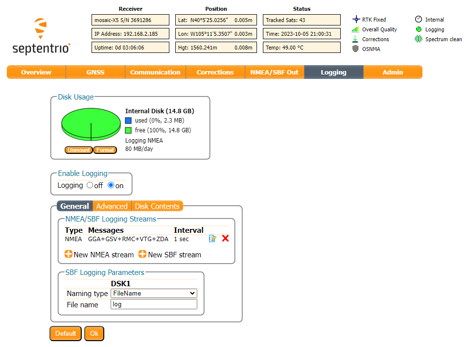
Once the stream is defined, users can control the data logging operation through the LOG button.
- A short press of the LOG button (< 5s) toggles data logging to the SD card on and off.
- The red
LOGLED will flash while logging is taking place. - A long press, holding the LOG button for more than 5 seconds (> 5s) and then releasing it, will force the board to:
- Unmount the SD card if it was mounted
- Mount the SD card if it was unmounted
SMA Connectors
The SXM-E has robust SMA connectors for the mosaic-X5 GNSS antenna and the ESP32 WiFi / BT antenna.
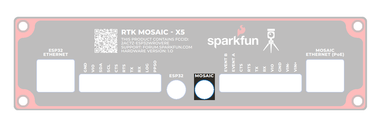
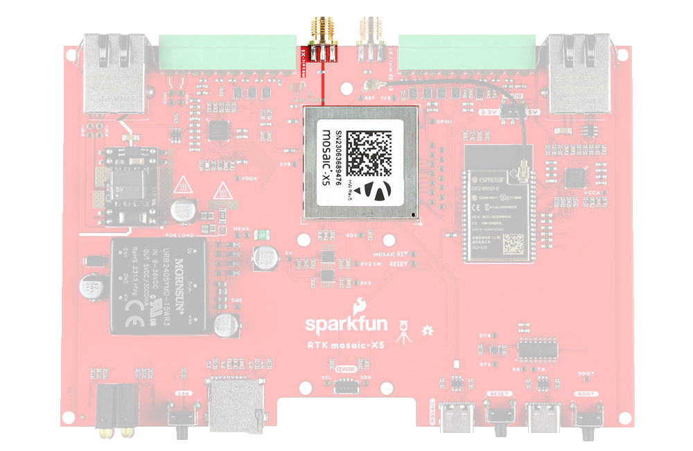
The mosaic-X5 SMA connector is standard polarity and provides 5V power for an active antenna.
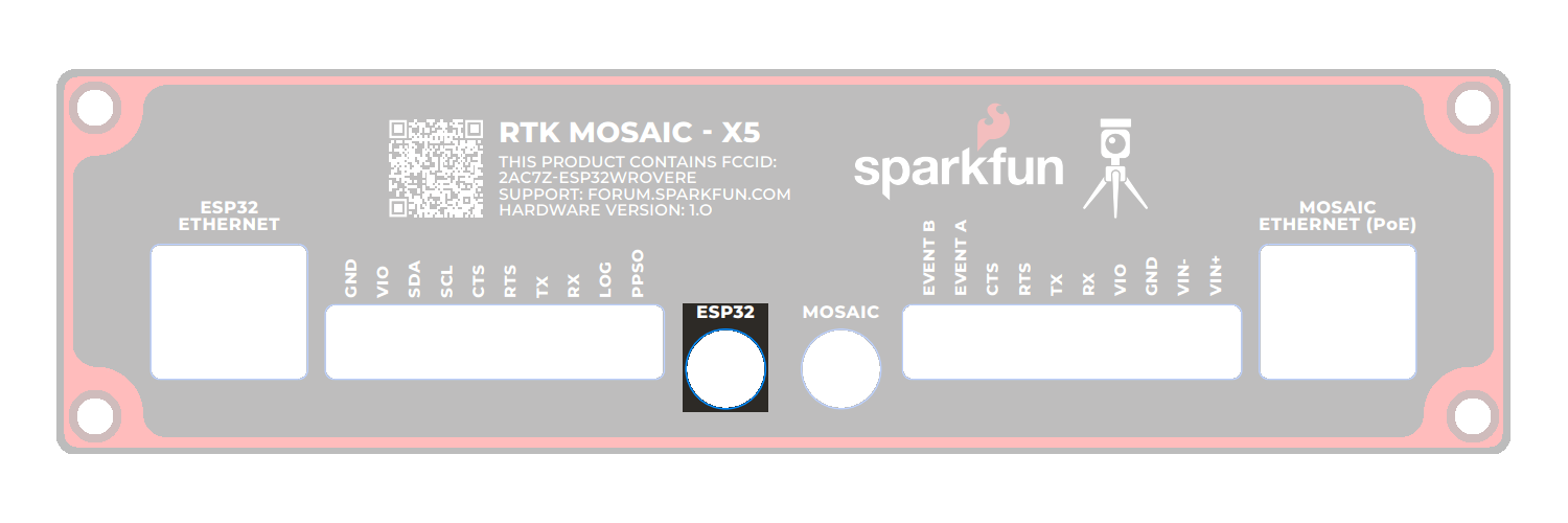
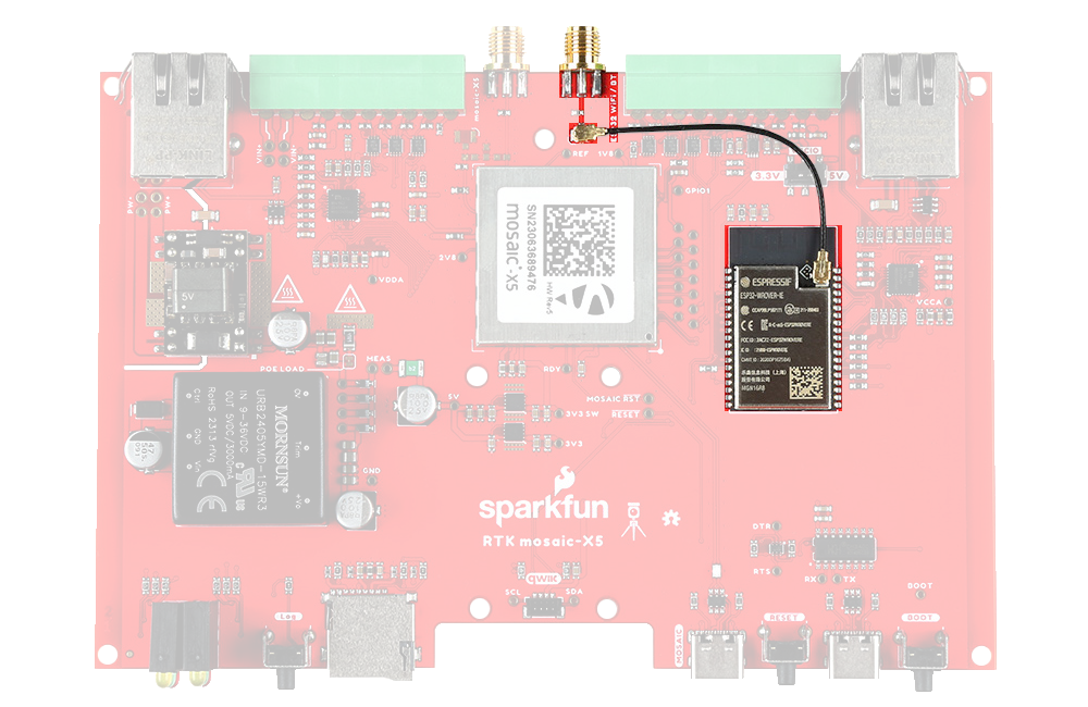
The ESP32 WiFi / BT SMA connector is reverse-polarity (RP). A short u.FL cable connects the SMA connector to the ESP32-WROVER itself.
When selecting antennas and/or cables for the SXM-E, double-check the polarity for the connections.
I/O Terminals
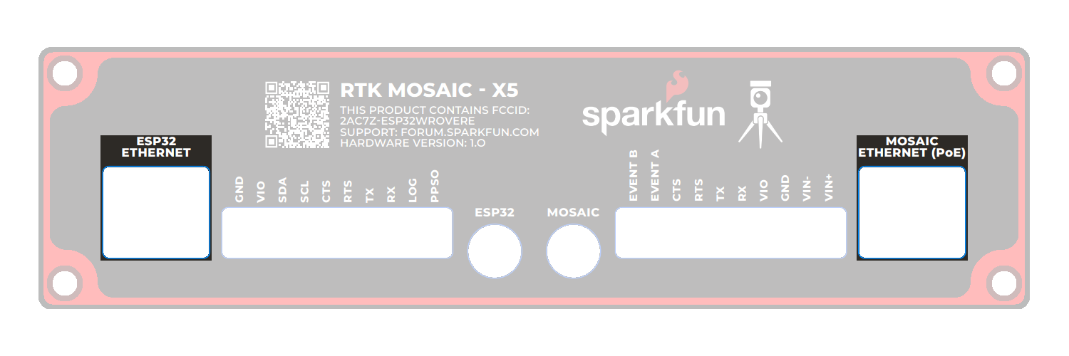
The RTK moasic-X5 is equipped with two 10-way 3.5mm screw cage terminal connectors.
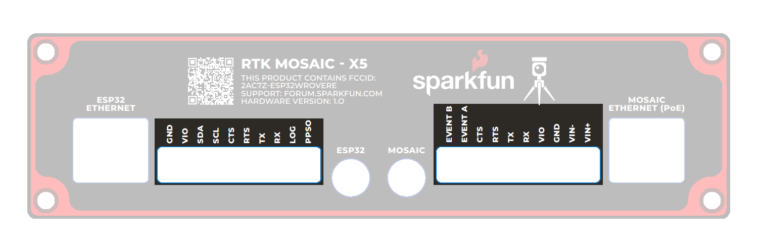
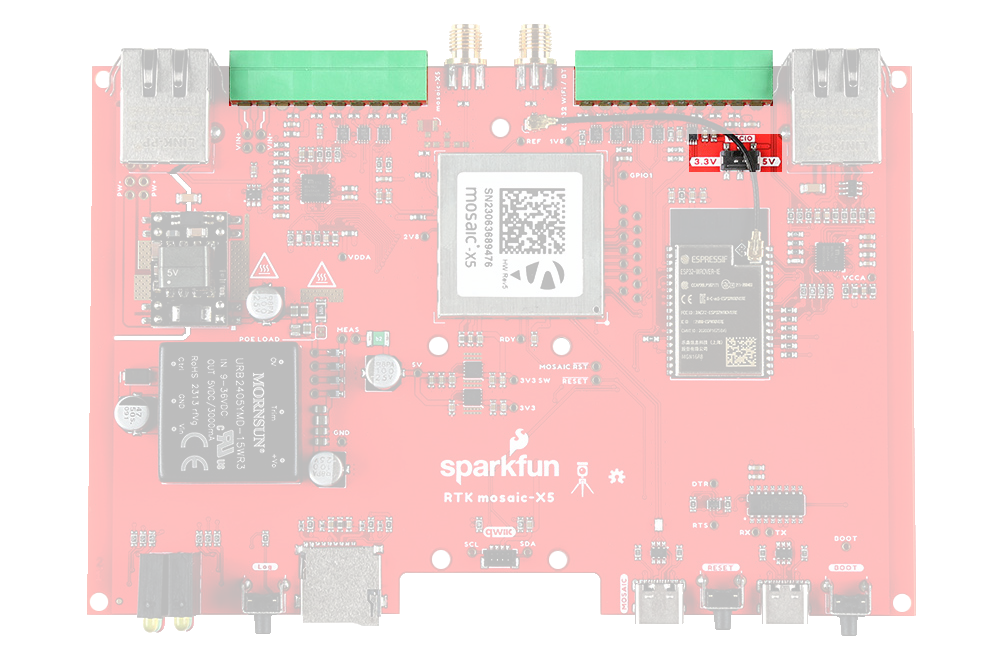
These terminals are described in the tabs below. For more information on the I/O terminals, you can refer to the schematic.
- External Power
- VIO & GND
- UART - mosaic-X5
- EVENT A & B
- PPSO
- LOG
- UART - ESP32
- SDA & SCL
The VIN+ and VIN- terminals allow the SXM-E to be powered by an external DC power source - typically a 12V / 24V vehicle battery.
| Terminal | Function |
|---|---|
| VIN+ | External voltage: Min: 9V; Max: 36V |
| VIN- | Ground / Chassis / 0V |
The DC-DC converter in the SXM-E provides 1.5kV isolation between VIN+/VIN- and 5V/GND. There is no direct electrical connection between VIN- and GND.
If desired, users can link VIN- to the adjacent GND screw cage terminal. However, this will bypass the voltage isolation and could introduce an unwanted ground loop, particularly if the GNSS antenna ground (shield, 0V) is also connected to the chassis.
The I/O terminal voltage can be set to 3.3V or 5V via the small internal slide switch highlighted below: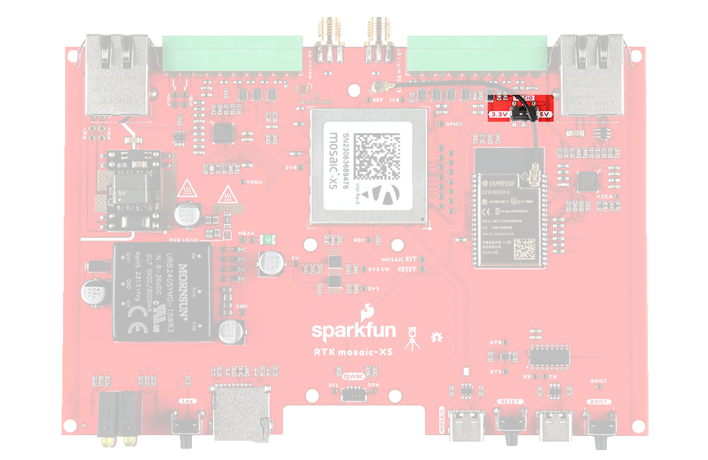
The VIO terminals can be used as power outputs or logic-high references. Likewise, the GND terminals can be used for power return or as logic-low references.
| Terminal | Function |
|---|---|
| VIO | 3.3V or 5V power output or logic-high reference |
| GND | Ground / 0V or logic-low reference |
The default position of the VIO switch is 3.3V.
The VIO and GND pins could be used to power (e.g.) a LoRa module. We recommend limiting the current draw from VIO to 200mA and never drawing more than 500mA peak. The upstream 3.3V regulator is rated at 1A but it also provides power for the ESP32 processor.
The mosaic-X5 UART COM1 connections are adjacent to the EVENTA and EVENTB terminals and are connected as follows:
| Terminal | Function | Notes |
|---|---|---|
| RX | COM1 UART Receive - Input | |
| TX | COM1 UART Transmit - Output | |
| RTS | COM1 UART Request To Send - Output | The module drives this pin low when ready to receive data |
| CTS | COM1 UART Clear To Send - Input | Must be driven low when ready to receive data from the module |
The COM1 I/O voltage is set by the I/O voltage selection switch.
The CTS input floats low. Pull CTS up to VIO to disable UART Transmit.
The mosaic-X5 EVENTA and EVENTB inputs can be used to mark or timestamp external events:
| Terminal | Function |
|---|---|
| EVENTA | Event A : Input |
| EVENTB | Event B : Input |
The EVENT voltage level is set by the I/O voltage selection switch.
The EVENT inputs are pulled low internally. Pull up to VIO to trigger an event.
An easy way to observe the events is with RxTools \ RxControl \ Expert Console (under Tools) \ ExEvent tab: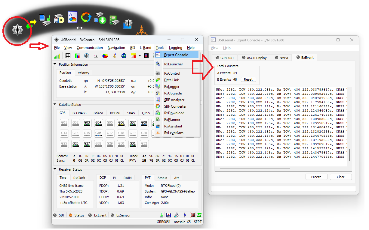
The mosaic-X5 PPSO is a configurable Pulse-Per-Second output. By default, PPSO is high for 5ms at 1Hz. The polarity, frequency and pulse width can be adjusted with the setPPSParameters command.
| Terminal | Function |
|---|---|
| PPSO | Pulse-Per-Second : Output |
The PPSO voltage is set by the I/O voltage selection switch.
The mosaic-X5 LOG input starts and stops µSD logging. It is also used to mount and dismount the µSD card.
| Terminal | Function |
|---|---|
| LOG | Log : Input |
The LOG voltage level is set by the I/O voltage selection switch.
The LOG input is pulled up to VIO internally. Pull low to GND to start or stop logging.
Internal resistors allow the LOG I/O terminal and Log button to be used simultaneously. It is OK to press the Log button while the LOG terminal is being driven high (VIO).
Four ESP32 GPIO pins are connected to I/O screw terminals as follows. These pins are not used by version 1.0.0 of the SXM-E ESP32 firmware. They are available for you to use if you are developing your own firmware.
| Terminal | Suggested Function | Notes |
|---|---|---|
| RX | UART Receive | Input - connected to GPIO pin 34 through a level-shifter |
| TX | UART Transmit | Output - connected to GPIO pin 32 through a level-shifter |
| RTS | UART Request To Send | Output - connected to GPIO pin 33 through a level-shifter |
| CTS | UART Clear To Send | Input - connected to GPIO pin 35 through a level-shifter |
The I/O voltage is set by the I/O voltage selection switch.
These pins are not used by version 1.0.0 of the ESP32 firmware.
The ESP32 I2C (Wire) bus SDA and SCL signals are available via the I/O terminals. Internally, the I2C bus is used to configure the Qwiic OLED display. If you connect a logic analyzer to the SDA and SCL I/O terminals, you will be able to see the OLED traffic (address 0x3D). We made the SDA and SCL signals accessible in case you are developing your own firmware for the SXM-E. The I/O terminals are fully level-shifted. It is OK to have a 5V I2C peripheral connected while also using the internal 3.3V Qwiic bus for the OLED.
| Terminal | Function |
|---|---|
| SDA | I2C Data |
| SCL | I2C Clock |
The I/O voltage is set by the I/O voltage selection switch.


The Qwiic connect system is a solderless, polarized connection system that allows users to seamlessly daisy chain I2C boards together. Play the video below to learn more about the Qwiic connect system or click on the banner above to learn more about Qwiic products.
- No Soldering
- Polarized Connector
- Daisy Chain-able


Qwiic cables (4-pin JST) plug easily from development boards to sensors, shields, accessory boards and more, making easy work of setting up a new prototype.


There's no need to worry about accidentally swapping the SDA and SCL wires on your breadboard. The Qwiic connector is polarized so you know you’ll have it wired correctly every time, right from the start.
The PCB connector is part number SM04B-SRSS (Datasheet) or equivalent. The mating connector used on cables is part number SHR04V-S-B or an equivalent (1mm pitch, 4-pin JST connector).

It’s time to leverage the power of the I2C bus! Most Qwiic boards will have two or more connectors on them, allowing multiple devices to be connected.
Status LEDs
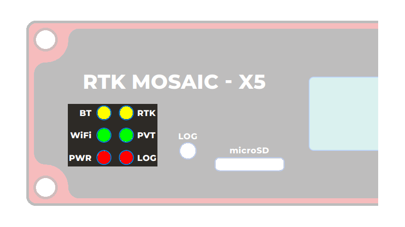
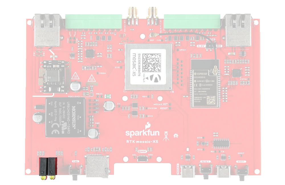
There are six status LEDs on the SXM-E:
PWR- Power (Red)- Illuminates when power is applied
LOG- µSD Logging (Red)- Solid Red - µSD card is mounted
- Blinking Red - Data is being logged
- Off - µSD is dismounted or not present
WiFi- WiFi (Green)- The ESP32 firmware is using WiFi
- Connected to ESP32 GPIO pin 12
PVT- Position Velocity Time (Green)- Solid Green - The mosaic-X5 has valid Position, Velocity and Time
- Off - Satellite signal not present or acquired
BT- Bluetooth (Yellow)- The ESP32 firmware is using BT
- Connected to ESP32 GPIO pin 13
- Not used by firmware v1.0.0
RTK- Real-Time Kinematic (Yellow)- Solid Yellow - The mosaic-X5 has an RTK Fixed solution
- Blinking Yellow - The mosaic-X5 has an RTK Float solution
- Off - No RTK solution
OLED Display
The SXM-E has a 128x64 pixel OLED display, controlled by the ESP32 via I2C. After some initial diagnostic messages, the display will show position, time and other data from the mosaic-X5 NMEA GGA message, plus the Ethernet / WiFi IP address.
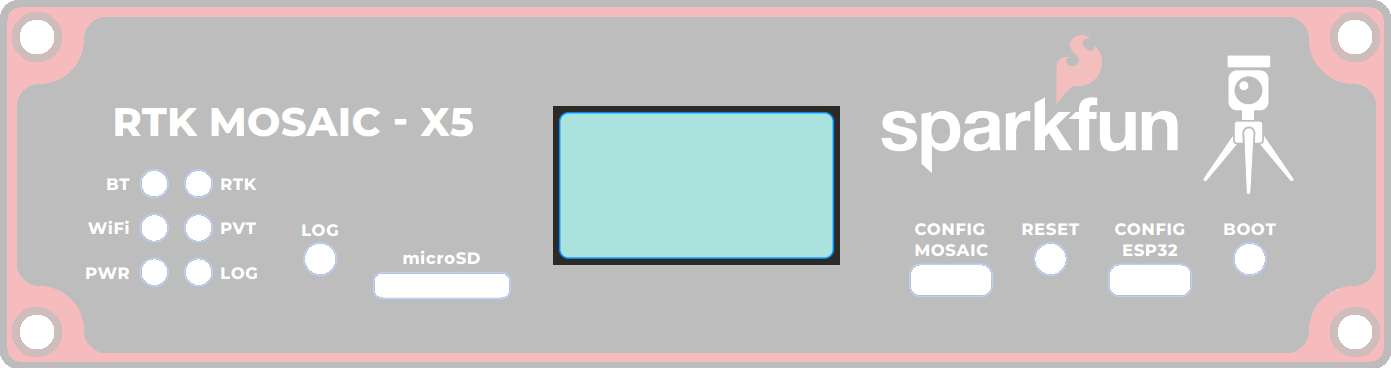
- Time: - Universal Time Coordinate (UTC) in
HHMMSS.SSformat- Note: the display is updated approximately every 2 seconds. The time shown may not be precise.
- Lat: - Latitude in
DDMM.MMMMMMMN/Sformat (this is the format used by the GGA message) - Long: - Longitude in
DDDMM.MMMMMMME/Wformat (this is the format used by the GGA message) - Fix: - the GNSS fix type
- Sat: - the number of satellites used in the navigation solution
- Note: this is not the same as "Satellites In View"
- HDOP: - Horizontal Dilution Of Precision
- Note: this is a dimensionless number indicating the horizontal position accuracy
- Alt: - the Altitude in meters
- Note: this is the altitude above Mean Sea Level, not Geoid
- IP: - the mosaic-X5 IP address, obtained via Ethernet or WiFi
- The X5's internal configuration page can be viewed at this address
Below, is an example data set recorded on the SXM-E at SparkFun HQ; where the antenna was located on the roof of the building. The antenna was above the loading dock, just about where it is displayed on the map. The table, below, is an example of how to convert the information on the display into the time and coordinate values.
| Data | Format | Value | |
|---|---|---|---|
| Time | 191525.90 | HHMMSS.SS | 7:15:25.90 PM (UTC) 12:15:25.90 PM (MST) |
| Latitude | 4005.4192485 N | DDMM.MMMMMMM N/S | 40° 5.4162485' N 40° 5' 24.97491" N 40.090270808° N |
| Longitude | 10511.0873663 W | DDDMM.MMMMMMM E/W | 105° 11.0873663' W 105° 11' 5.241978" W 105.184789438° W |
Buttons
There are three buttons on the SXM-E: RESET, BOOT, and LOG.
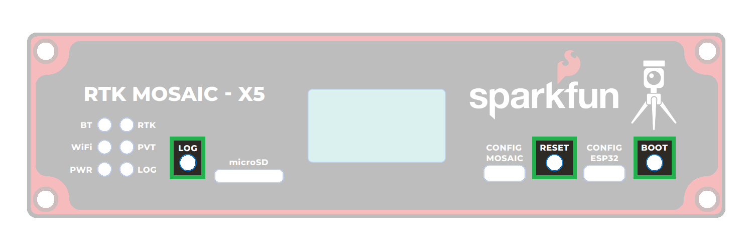
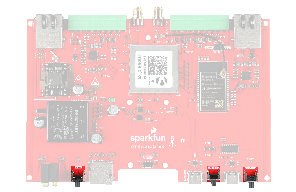
- mosaic-X5: Data Logging
- ESP32: Reset
- ESP32: Boot Control
Once a logging stream is defined, users can control the data logging operation through the LOG button.
- A short press of the LOG button (< 5s) toggles data logging to the SD card on and off.
- The red
LOGLED will flash while logging is taking place.
- The red
- Holding the LOG button for more than 5 seconds (> 5s) and then releasing it, will force the board to:
- Unmount the SD card if it was mounted
- Mount the SD card if it was unmounted
The RESET button allows users to reset the firmware running on the ESP32-WROVER module without disconnecting the power.
The BOOT button can be used to force the ESP32 into the serial bootloader. Holding down the BOOT button, while connecting the SXM-E to a computer through its USB-C connector or resetting the board will cause it to enter the Firmware Download mode. The ESP32 will remain in this mode until it power cycles (happens automatically after uploading new firmware) or the RESET button is pressed.
- Hold the BOOT button down.
- Reset the MCU.
- While unpowered, connect the board to a computer through the USB-C connection.
- While powered, press the RESET button.
- Release the BOOT button.
- After programming is completed, reboot the MCU.
- Press the RESET button.
- Power cycle the board.
The ESP32 GPIO pin 0 is connected to the BOOT button. But is also used by the firmware to generate the 50MHz clock for the RMII Ethernet PHY interface.
Pressing the BOOT button while the firmware is running in mode 2 (WiFi) will interrupt the clock and cause Ethernet communication with the mosaic-X5 to fail.
Jumpers
Check out our Jumper Pads and PCB Traces tutorial for a quick introduction!
How to Work with Jumper Pads and PCB Traces
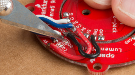
Check out our Jumper Pads and PCB Traces tutorial for a quick introduction!
There are several jumpers on the RTK moasic-X5 PCB which can be used to (e.g.) disable the LEDs or allow measurement of the board's current draw.
- Top
- Bottom
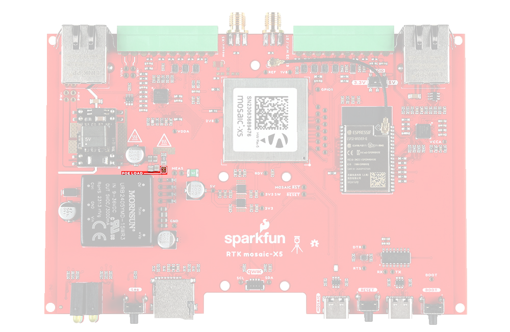
- POE LOAD - This jumper can be used to disconnect the Power-over-Ethernet (PoE) module 50Ω load.
- The PoE module has a minimum load of 100mA. We included the 50Ω load to ensure this is met. If you can ensure this by other means, open this jumper to disconnect the load.
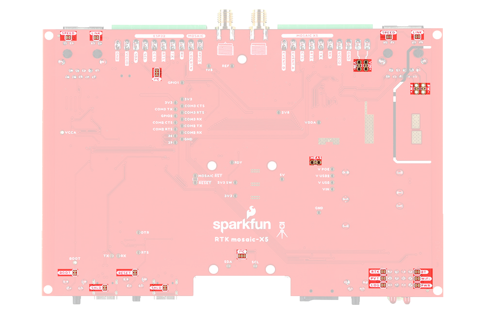
- LED Jumpers
- LINK (x2) - open these jumpers to disable the Ethernet Link LEDs.
- SPEED (x2) - open these jumpers to disable the Ethernet Speed LEDs.
- RTK - open this jumper to disable the mosaic-X5 Real-Time Kinetic LED.
- PVT - open this jumper to disable the mosaic-X5 Position Velocity Time LED.
- LOG - open this jumper to disable the mosaic-X5 Log LED.
- BT - open this jumper to disable the ESP32 BT LED.
- WiFi - open this jumper to disable the ESP32 WiFi LED.
- PWR - open this jumper to disable the Power LED.
- Button Jumpers
- BOOT - open this jumper to disconnect the ESP32 BOOT pushbutton.
- RESET - open this jumper to disconnect the ESP32 RESET pushbutton.
- SHLD (x2) - open these jumpers to isolate the USB-C connector shield from GND.
- I2C - open this dual jumper to disconnect the pull-ups for the SDA and SCL I/O terminals.
- Note: the internal 3.3V Qwiic bus has its own pull-ups which are disconnected by default. These can be enabled by closing the dual jumper under the OLED Qwiic connector. We suggest you only do this if you are disconnecting the OLED.
- VIN+ and VIN-
- Open these jumpers if you wish to isolate (disconnect) the external DC power terminals. The breakout pads can then be used to feed in power from an alternate source.
- PW+ and PW-
- Open these jumpers if you wish to isolate (disconnect) the Power-over-Ethernet pins on the MOSAIC Ethernet magjack. The breakout pads can then be used to feed in power from an alternate source.
- MEAS
- Open the MEAS jumper if you wish to measure the total current drawn by the SXM-E, or (e.g.) wish to add an ON/OFF switch. The breakout pads can then be used to attach a multimeter or a mechanical power switch.
- MEAS is upstream of the two 3.3V regulators and downstream of the four power source combination and protection diodes.