Quick Start: WiFi Setup
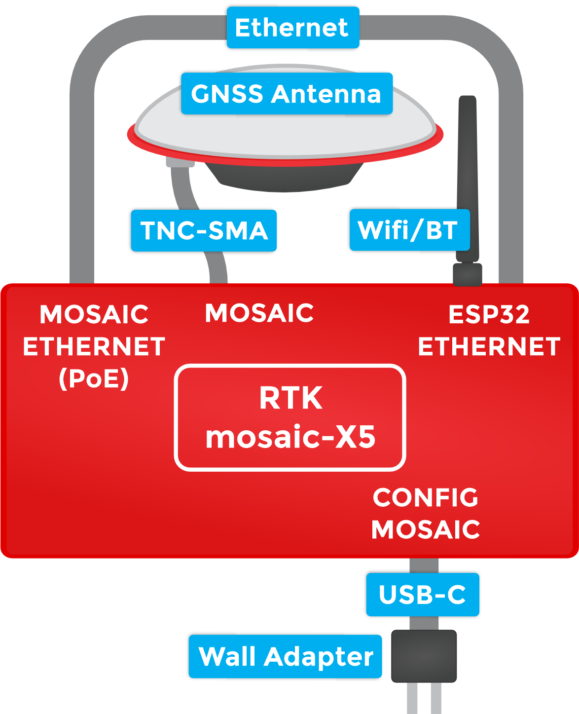
The mosaic-X5 GNSS module supports multiple communication interfaces: multiple UARTs; Ethernet; and USB-C (with Ethernet-over-USB). But it does not support WiFi directly. The SXM-E contains an ESP32-WROVER processor which can act as an Ethernet to WiFi bridge. By linking the MOSAIC ETHERNET (PoE) port to the ESP32 ETHERNET port and putting the ESP32 firmware into WiFi mode, the mosaic-X5 can join your WiFi network.
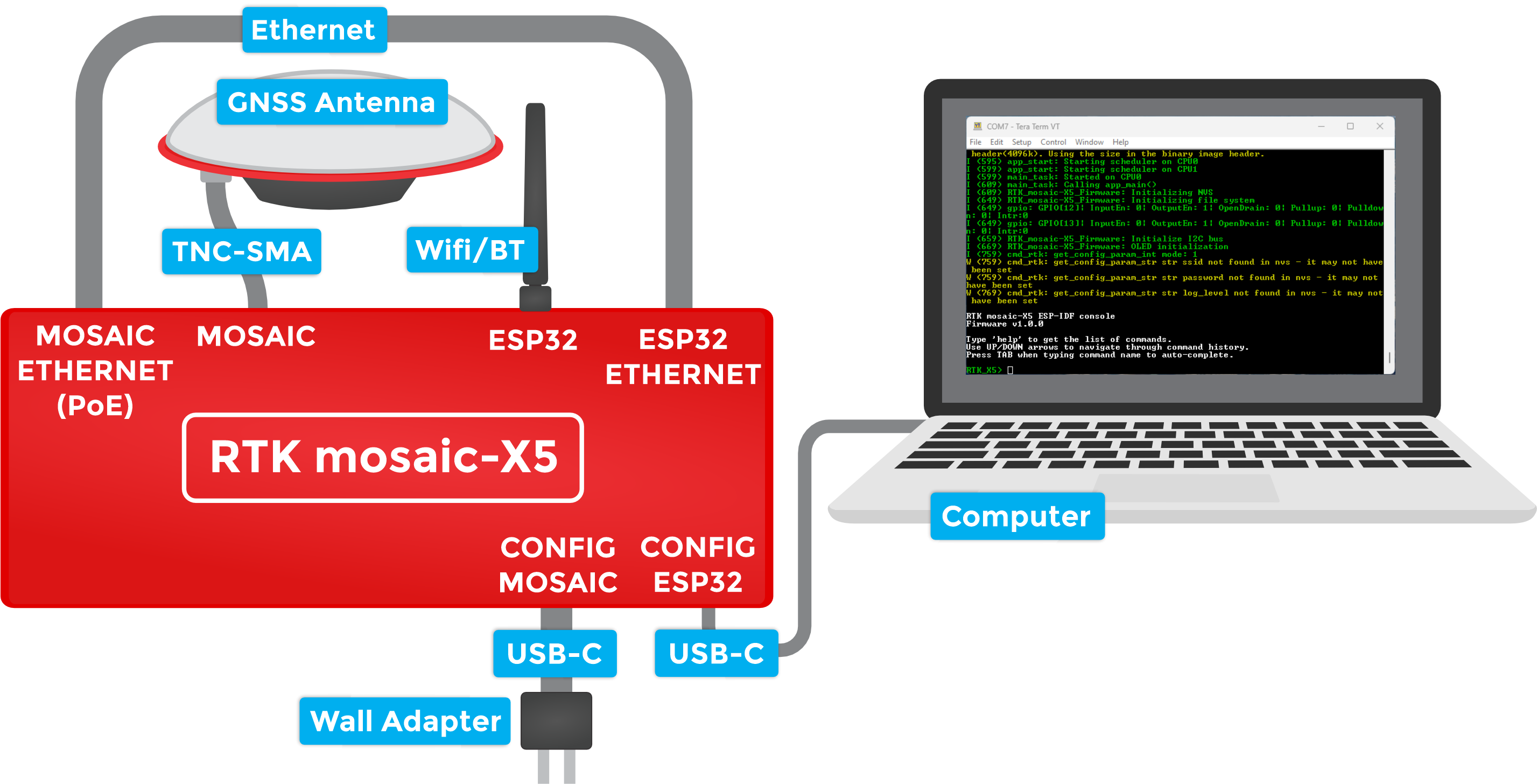
To connect your SXM-E to WiFi, you need to do a little more work including changing the mode of the firmware running on the ESP32 processor.
1 - Connect the GNSS antenna
- Inside your SXM-E kit, you will find the L1/L2/L5 GNSS "UFO" antenna. It has a TNC connection. Use the supplied TNC-SMA cable to connect the antenna to the mosaic-X5 MOSAIC SMA connection.
- The antenna needs a clear view of the sky. If you are working indoors, put the antenna outside and pass the cable through a window. (Insulating double-glazed windows have a coating, which can block the GNSS signal. For best results, put the antenna outside.)
- If you are going to use your SXM-E as a continuously operating reference station (CORS), the antenna needs to be securely mounted to a structure so that it cannot be moved and has a clear view of the sky. Any movement in the antenna will cause inaccurate readings by RTK rovers. We recommend using our GNSS Antenna Mounting Hardware Kit or GNSS Magnetic Antenna Mount - 5/8" 11-TPI.
2 - Attach the WiFi antenna
- Screw the supplied WiFi/BT antenna onto the ESP32 SMA connection.
- To minimize wear of the SMA connector, we recommend: holding the antenna body with one hand - to prevent it from rotating - while screwing the SMA connector into place with your other hand.
- Fold the antenna up if needed, so the antenna body is vertical.
3 - Link the Ethernet ports
- Link the MOSAIC ETHERNET (PoE) and ESP32 ETHERNET ports using the supplied cable.
- The Ethernet ports support Auto-MDIX. You can use a standard Ethernet patch cable to link the ports. You do not need a crossover cable.
4 - Connect to the CONFIG ESP32 USB port
- To change the ESP32 firmware mode, you need to connect a computer to the
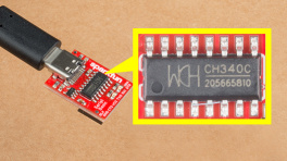
CONFIG ESP32USB-C port and use a Serial Terminal to change the mode. - You may need to install a driver, first, so that the CH340 serial interface chip is recognized. Please click the bar below for more details.
Users may need to install the appropriate USB driver for their computer to recognize the serial-to-UART chip on their board/adapter. Most of the latest operating systems will recognize the CH340C chip on the board and automatically install the required driver. To manually install the CH340 driver on their computer, users can download it from the WCH website.
For users having trouble installing the CH340 USB driver, check out our video and hookup guide:
How to Install CH340 Drivers
5 - Open a Serial Terminal
- If you are using Windows, we still recommend the Tera Term serial terminal but there are plenty of alternatives. Please see our Serial Terminal Basics tutorial for more details.
- Open the connection to the CH340 using 115200 baud
6 - Put the ESP32 firmware into WiFi mode
-
When you have the Serial Terminal open, you should see the
RTK_X5>console prompt. If you do not, hit Enter on your keyboard. If needed, click the RESET button on the front of the SXM-E to restart the ESP32 firmware.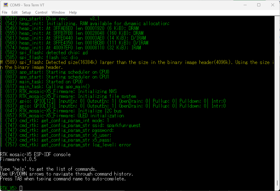
RTK_X5>in the console prompt -
Type
helpand hit enter to see the help.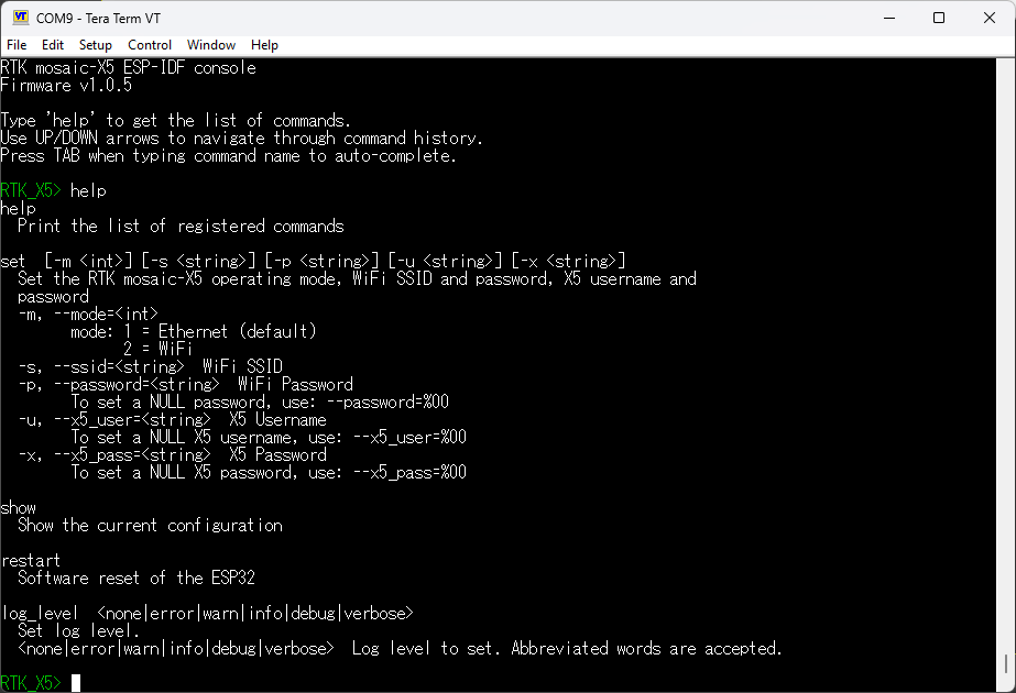
Output from helpcommand -
Type
showto see the current configuration.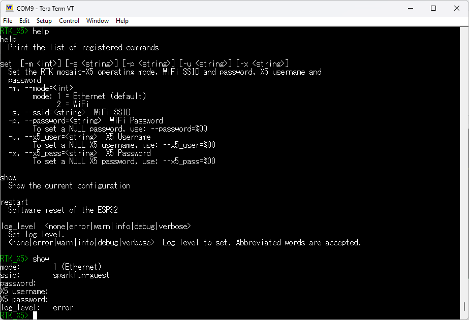
Output from showcommand -
By default the firmware will be in Mode:
1(Ethernet). To change the mode to Mode:2(WiFi), we type:set -m 2Long ArgumentsThe console supports both short and long args, so we could type:
set --mode=2 -
To set the WiFi SSID, type one of:
set -s YOUR_SSIDset --ssid=YOUR_SSID- Likewise, to set the WiFi password, type one of:
set -p YOUR_PASSWORDset --password=YOUR_PASSWORD
- To save time, you can set all three together with one of:
set -m 2 -s YOUR_SSID -p YOUR_PASSWORDset --mode=2 --ssid=YOUR_SSID --password=YOUR_PASSWORD
- Likewise, to set the WiFi password, type one of:
-
Finally, type
restartto restart the firmware with the new settings:restartNULL (empty) passwordTo clear the password - making it NULL / empty - type one of:
set -p %00set --password=%00
Once the mosaic-X5 has acquired a satellite signal and is connected to the WiFi network, the OLED will display: the antenna's position as Latitude (Lat), Longitude (Long) and Altitude (Alt); the WiFi IP (Internet Protocol) network address.
When powering the SXM-E on for the first time, you may see the firmware restart (reboot) several times while it waits for the mosaic-X5 to initialize. This is not an error or anything to be concerned about.
Connect your computer, tablet or phone to the same network, open a web browser and navigate to the IP address shown on the OLED display. You should see the mosaic-X5's internal web page. The web page displays a lot of helpful information and can also be used to fully configure the mosaic-X5.
The firmware mode, SSID and password are stored in flash (non-volatile) memory. After changing them, you can disconnect the computer and power the SXM-E using the supplied wall adapter.
The following sections will help if your SXM-E is not working as expected:
With mosaic-X5 firmware 4.15.1, a user-defined username and password are mandatory on all IP interfaces. These must be entered as described in the Log-in procedure on all IP interfaces individually and separately. The ESP32 is connected via COM. It does not need to know the username and password unless you also change default access level for the COM ports. If you do, you need to ensure the SXM-E ESP32 firmware has been upgraded to version >= 1.0.5 and that the username and password have been set using set -u and set -x
The red power (PWR) LED will light up when the SXM-E has power. If the PWR LED is off, make sure the wall adapter has power and the USB cable is connected.
The OLED display will only show position information (Lat, Long, Alt etc.) once a satellite signal has been acquired. If you see only an IP address on the display, check the SMA to TNC cable is connected correctly and that the antenna is outside with a clear view of the sky. Use a male-female SMA extension cable if needed to increase the cable length.
The mosaic-X5 Ethernet port is configured for Dynamic Host Configuration Protocol (DHCP). It expects the WiFi network to provide it with an IP address. If the IP address is all zeros (0.0.0.0), check that your router has DHCP enabled. Most do.
Subnet 3 is reserved for the mosaic-X5's USB-C connection (Ethernet-over-USB). If your router / switch is allocating addresses using subnet 3 (192.168.3.***), please change its settings so it uses a different subnet.
If you can not see the mosaic-X5's internal web page, please check that your computer / tablet / phone is connected to the same network. Most broadband routers support both Ethernet and WiFi simultaneously using the same subnet. If you are using a phone, check it is connected to the router WiFi - and not using its mobile data connection.
Subnet 3 is reserved for the mosaic-X5's USB-C connection (Ethernet-over-USB). If your router / switch is allocating addresses using subnet 3 (192.168.3.***), please change its settings so it uses a different subnet. If it is using subnet 3, both the mosaic-X5 and your device will appear to have valid IP addresses but will not be able to communicate.
If you still can not see the mosaic-X5's internal web page, please check that the ESP32 firmware is in the correct mode. Press the RESET button to restart the ESP32 and watch the text, which scrolls up the OLED display. You should see Mode 2: WiFi displayed briefly. If you see Mode 1: Ethernet, the firmware is in the wrong mode. Follow the instructions above to change the mode to 2 (WiFi).