Technical Support
If you need technical assistance or more information on a product that is not working as you expected, please head over to our SparkPNT Forum. Feel free to check out our troubleshooting tips, below, for some suggestions on common topics. By posting on the forum you benefit other users with similar questions. It also gives us feedback as a whole about where our products and documentation need improvement.
On your first visit to our forum, you'll need to create a Forum Account to post questions.
Order and Shipping Issues
If your order was damaged or is missing any parts, please email our support team at support@sparkpnt.com. Please, include your order number and a clear picture of your package's condition on arrival or showing any missing items.
If your order was placed through one of our distributors, please contact them first to resolve any issues.
By including information and images of the issue, our support staff can transfer you to the appropriate service team, who can get a jump start on a resolution to the problem.
Returns Process
For more details on our returns process, check out our full Return Policy.
Troubleshooting Tips
Below are some tip to troubleshoot common issues that users may come across.
What should be in the Box?
The SparkPNT SXM-E comes packaged as a complete kit, with all the accessories you'd need to set up an RTK base station or NTRIP server. Inside the kit, users will find the SXM-E, GNSS antenna, and another box containing additional accessories. Inside, the accessory box, users will find the CAT-6 Ethernet cable, USB cable, SMA to TNC cable, USB power supply, WiFi antenna, a pack of silicone bumpers, and 32GB SD card.
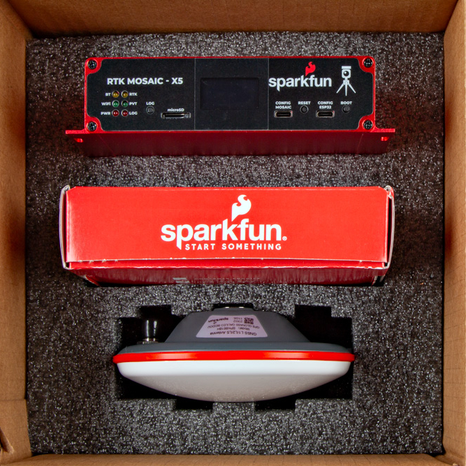
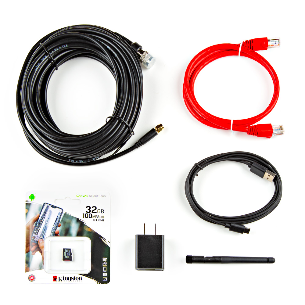
If you are missing any of these items, please email our support team at support@sparkpnt.com. Please, include your order number and a clear picture of your package's condition if it was damaged or showing any missing items.
WiFi Connectivity
For WiFi connectivity issues, here are some simple troubleshooting tips:
- Verify that the SXM-E is operating in Mode:
2for WiFi functionality. - Double-check the WiFi credentials used in the ESP32 configuration.
- Make sure that the configured WiFi network is broadcasting on a 2.4GHz band. The ESP32 cannot access the 5GHz band.
- Make sure that the Ethernet cable is not coiled around/near the WiFi antenna. This will cause data packets to be lost and the mosaic-X5 web page to hang/freeze.
WiFi Provisioning
The ESP32 firmware we provide is only compatible with basic SSID and Password WiFi authentication. The firmware is not compatible with networks that implement other provisioning methods such as a captive portal, a QR code, or Wi-Fi protected setup. Our intention was that users could easily develop their, own firmware to suit their needs.
Here are some resources that might be useful for getting started with other provisioning methods:
Data Logging
For data logging issues, here are some simple troubleshooting tips:
- Make sure that your SD card is formatted to a
FAT32file system.- The
FAT32file system also limits the maximum capacity of the card to less than 32GB (i.e. a 256GB SD card will not work).
- The
- Make sure that the mosaic-X5 module has a configured data stream output.
- Use the mosaic-X5 web page to verify that the SD card is mounted as a storage drive.
OLED Dead Pixels
Got a few dead pixels on your OLED display? Please email our support team at support@sparkpnt.com and include your order number with a clear picture showing the dead pixels.
Vehicle Power - Dead Battery
Is the SXM-E killing your vehicle's battery?
Make sure that the external power source for the SXM-E is not directly tied to the vehicle's battery, Always On, or accessory circuits. Otherwise, users will risk killing the battery while the engine is off. We recommend locating the ignition on or switched power circuit, which is only powered when the key is in the On position and the engine is running.
The On position, is where a key normally rests after the engine is started. However, users can still move the key from the Off position and into the On position without starting the engine. In this case, the alternator is not running and keeping the battery charged.
Modern eco-efficient vehicles may automatically shut down the engine if the vehicle is idling too long. Therefore, cutting off the vehicle's alternator that keeps the battery charged. Luckily, most vehicles with this automatic start/stop technology will monitor the battery's voltage and restart the engine when required. With this in mind, users may want to initially monitor their battery voltage, in case their vehicle isn't "so smart" 😅.
L5 Band
By default, the L5 band is disabled on the mosaic-X5. To enable reception of the L5 band on the mosaic-X5, we have provided instructions on the Enable the L5 Band page.
Expected Accuracy
Here is a reference of the accuracy that can be expected from the SXM-E at a stationary position in Rover mode.
- Factory Settings
- L5 Band Enabled
- RTK Corrections
- RTK & L5 Band
With the factory settings for the mosaic-X5, our location had a standard deviation of σx = 0.499m and σy = 0.595m
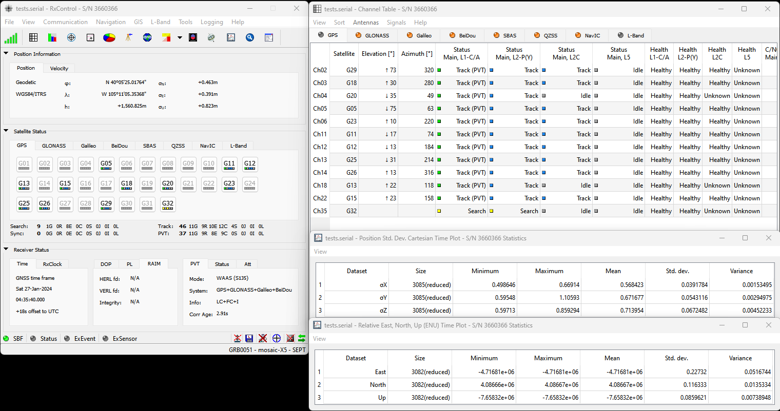
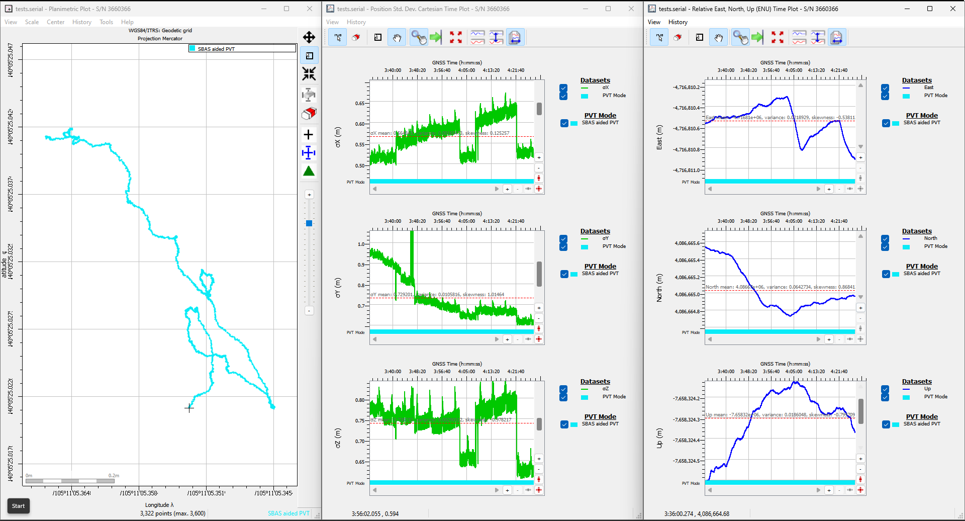
Conditions: L1/L2/L5 band antenna, statically mounted to the rooftop of our building, featuring a significant ground plane, with no obstructions for multi-path signals. The SXM-E was connected with a low-loss cable, fully powered at 5V, and default settings.
With the default settings and the L5 band enabled for the mosaic-X5, our location had a standard deviation of σx = 0.504m and σy = 0.673m
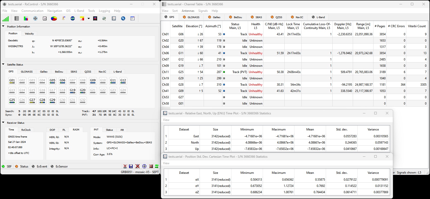
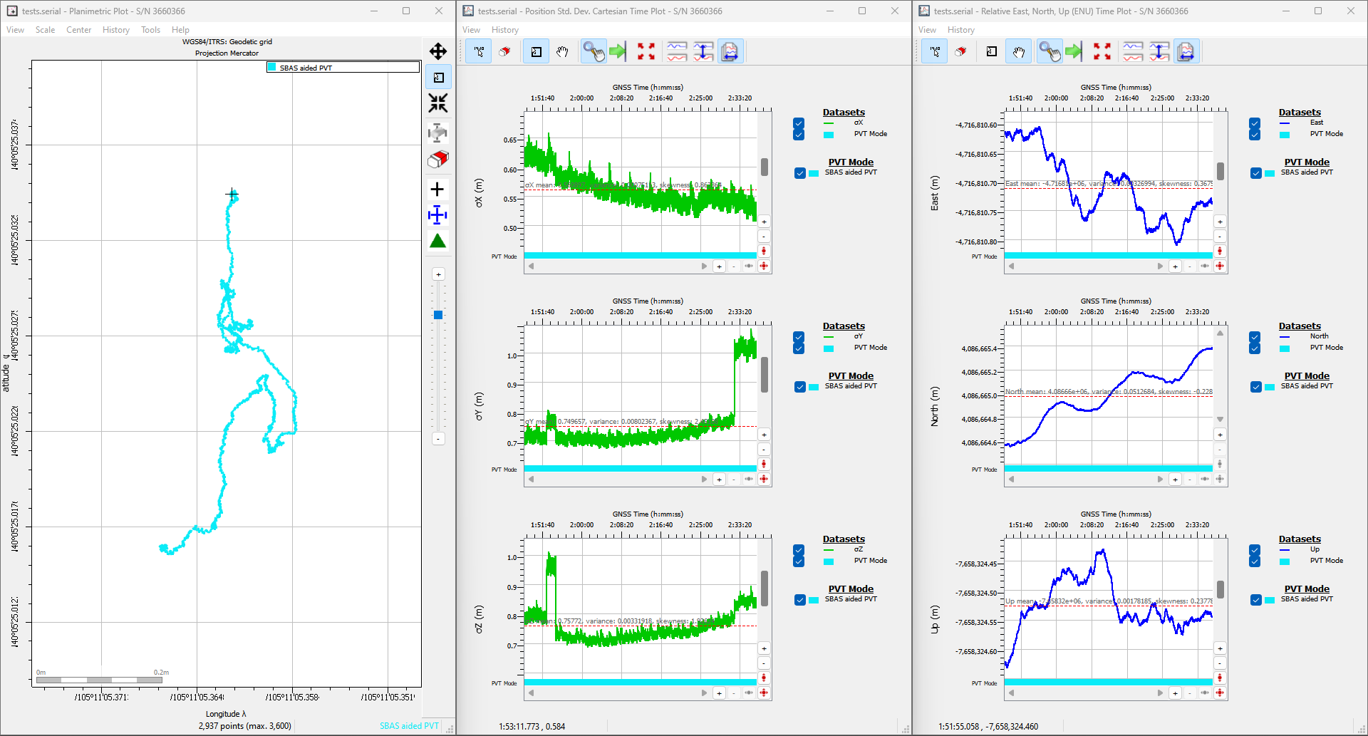
Conditions: L1/L2/L5 band antenna, statically mounted to the rooftop of our building, featuring a significant ground plane, with no obstructions for multi-path signals. The SXM-E was connected with a low-loss cable, fully powered at 5V, and had the L5 band enabled.
With the default setting and RTK corrections enabled for the mosaic-X5, our location had a standard deviation of σx = 4.29mm and σy = 6.65mm
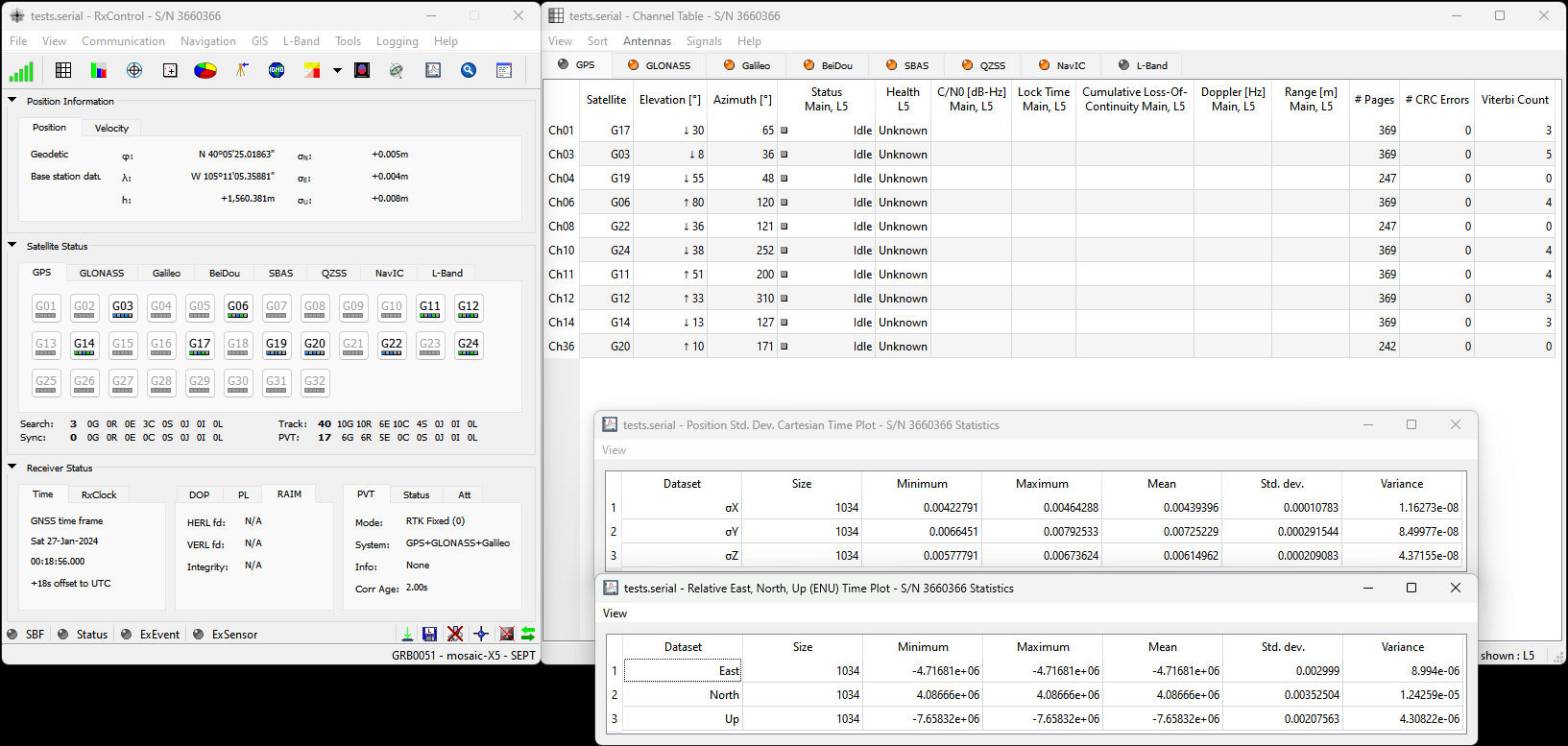
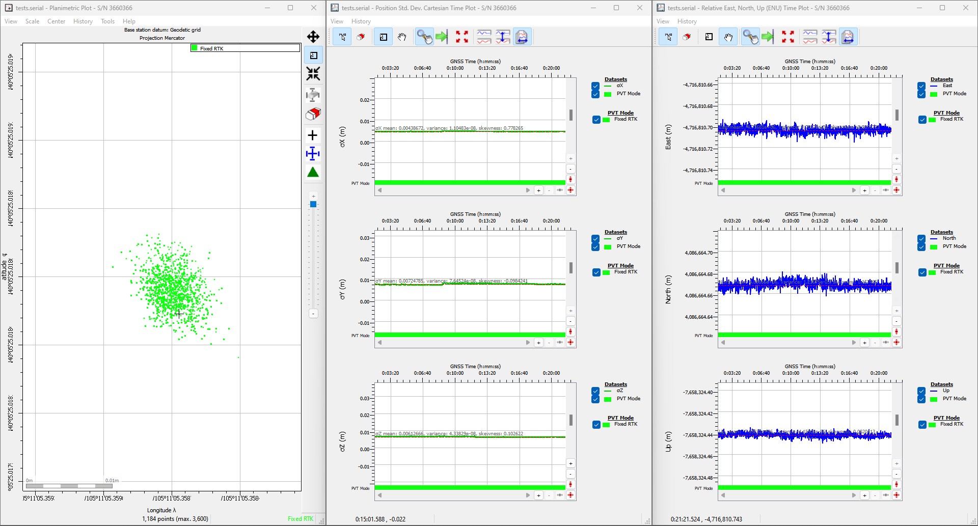
Conditions: L1/L2/L5 band antenna, statically mounted to the rooftop of our building, featuring a significant ground plane, with no obstructions for multi-path signals. The SXM-E was connected with a low-loss cable, fully powered at 5V, and configured as an NTRIP client with corrections from RTK2go. The baseline distance between the rover and base station was ~1m.
Under "ideal conditions", our location had a standard deviation of σx = 4.68mm and σy = 6.70mm
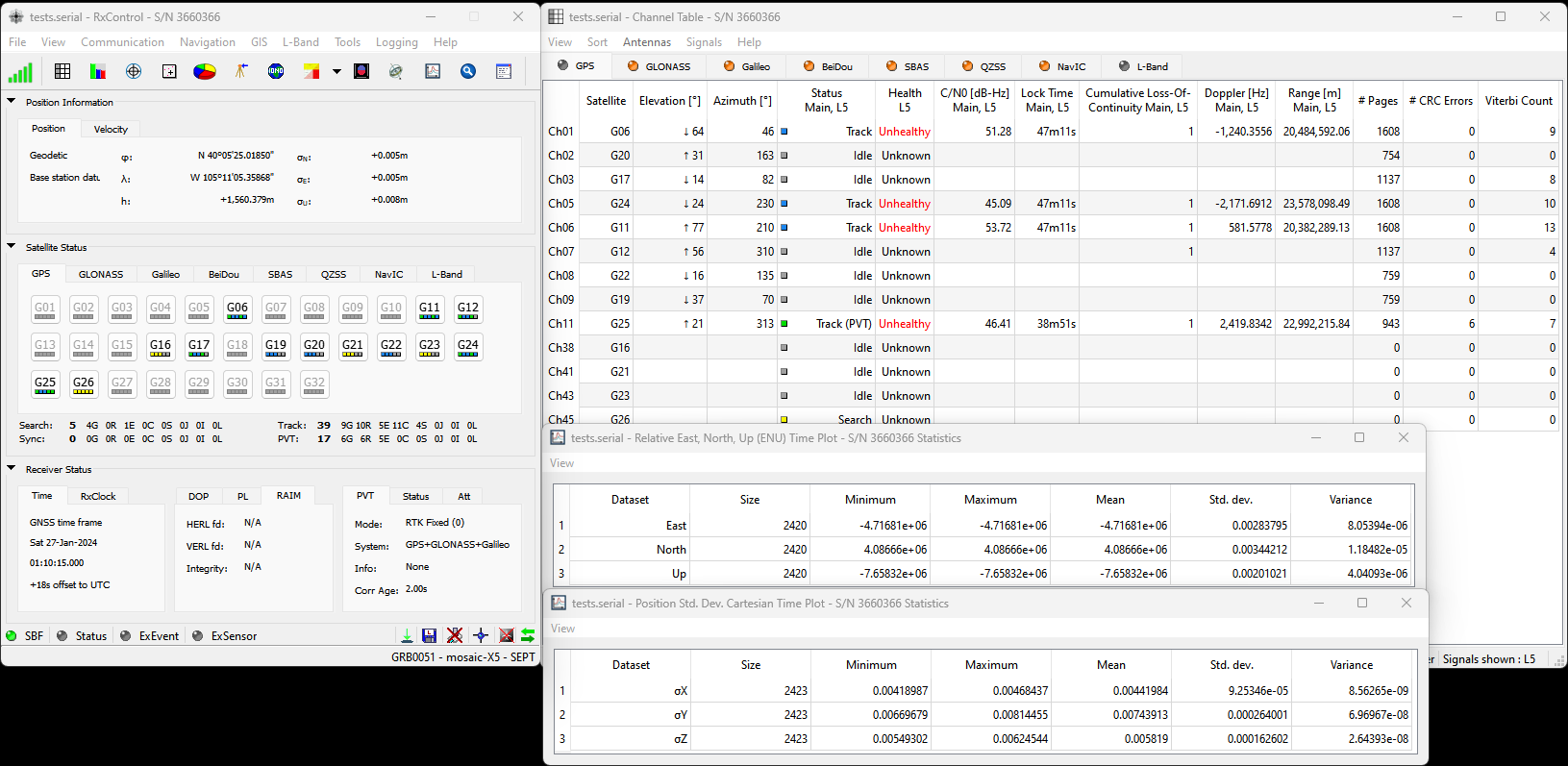
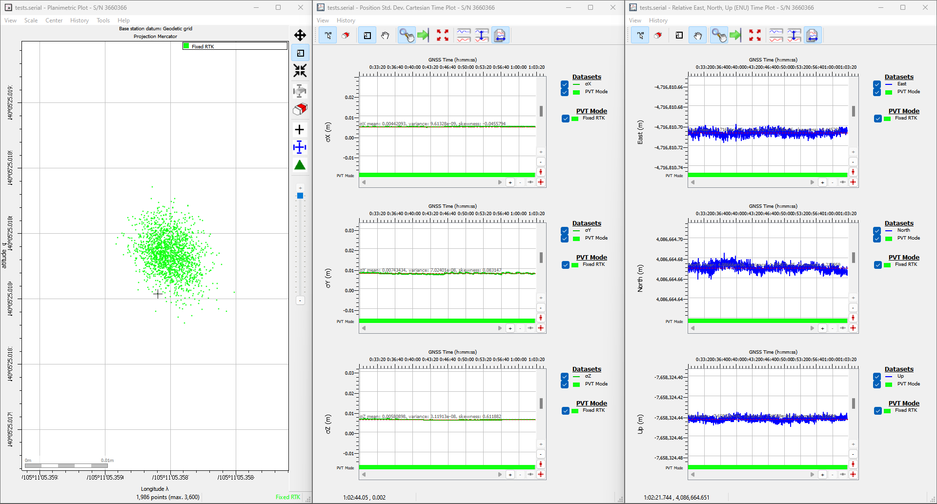
L5 band enabled.
Conditions: L1/L2/L5 band antenna, statically mounted to the rooftop of our building, featuring a significant ground plane, with no obstructions for multi-path signals. The SXM-E was connected with a low-loss cable, fully powered at 5V, RTK corrections enabled, and configured as an NTRIP client with the L5 band enabled, using corrections from RTK2go. The baseline distance between the rover and base station was ~1m.
Reprogramming the ESP32
In case users accidentally reprogram or corrupt the flash memory on the ESP32, the factory firmware is available in our GitHub repository.
The batch files in the linked directory are used to flash our factory firmware onto the ESP32 in the SXM-E. The batch file relies on the tools from the Arduino IDE and the ESP32 Arduino core and therefore, they will need to be installed before the batch file can be executed.
The batch file is only compatible with Windows computers. For Linux and MacOS, users will need to manually flash the binary files onto the ESP32.
To compile the firmware, users will need to install the ESP-IDF, Espressif's development framework for the ESP32. However, the compilation instructions are outside the scope of our support for this product. However, users can refer to the programming guide for the ESP-IDF to figure out how to compile the firmware.
mosaic-X5 Security Credentials
Beginning with firmware v4.15.0+, Septentrio has introduced a mandatory user login requirement. For more details, please refer to the following articles:
- Username:
RxAdmin
- Password:
S3pt3ntr10
Once configured, the users credentials will be stored in memory. These settings will be
The serial ports (COM and USB-COM) remain accessible by default, without login credentials.
This access can be restricted to logged-in users, if enhanced physical access control is required. However, we recommend absolute caution before implementing these access control restrictions.
We do not have any methods to restore the credentials to their factory defaults, if users can't access the serial ports.
Enclosure Disassembly
Due to the ESD sensitivity of the mosaic-X5 module, we don't recommend disassembling the SXM-E. However, if users must access the PCB to troubleshoot an issue, make a modification, or repair a component, we highly recommend that they take the necessary ESD precautions to avoid damaging the mosaic-X5 module.
The mosaic-X5 module is sensitive to ESD. Use a proper grounding system to make sure that the working surface and the components are at the same electric potential.
As recommended by the manufacturer, we highly encourage users to take the necessary precautions to avoid damaging their module.
- The PCB is not grounded through the enclosure.
- The PCB features ESD protection on the USB-C connectors and ethernet jacks.
- The mosaic-X5 module also has ESD protection from the
ANT_1antenna input.
iFixit Anti-Static Wrist Strap
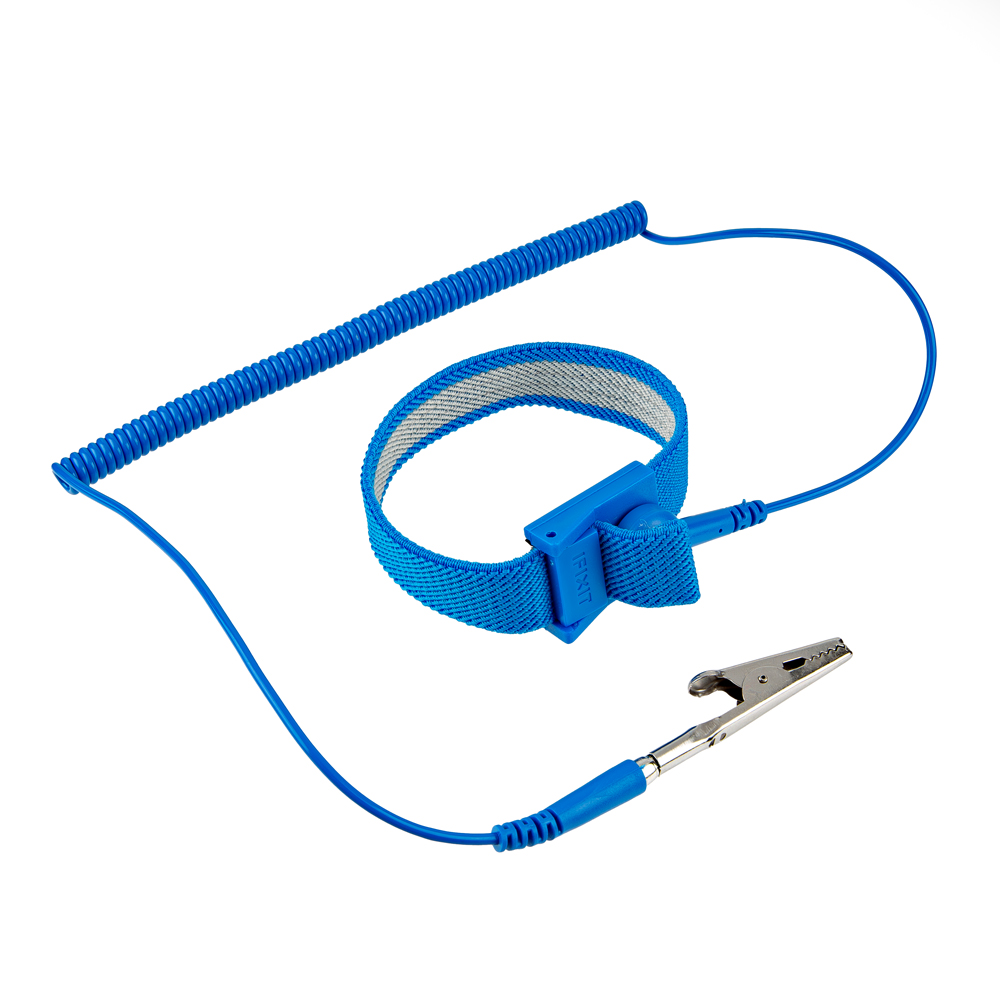
Before disassembling the enclosure, users should disconnect the power and all cables from the SXM-E. This will prevent users from creating any shorts and facilitate the teardown process further on.
The internal PCB is only held in place by the front and rear panels of the enclosure. While users can remove the panels first, we recommend that users disconnect the pluggable screw terminal blocks first. Users may find it more difficult to separate the pluggable terminal block from the PCB later in the disassembly process.
-
Users may find it easiest to disconnect the pluggable terminal blocks first; as opposed to later in the teardown process. Users can wiggle or use a soft/rigid object to carefully pry the terminal block off.
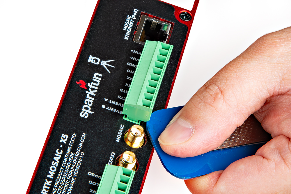
Carefully pry the pluggable terminal blocks off. tipIn the picture above, a plastic name tag (~1.5mm thick) is used to carefully pry the terminal block up. We have also found the edge of a PCB ruler works great too.
-
Once the pluggable terminal blocks have been removed, users can remove the front and rear panels of the enclosure. They are held in place with four, M3, Phillips head screws on the corners of each panel.
tipWe recommend removing the front panel first to prevent the Qwiic cable from being yanked off the OLED display or main PCB. Once the front panel is free, carefully lift the panel from the enclosure and disconnect the Qwiic cable from the top connector on the OLED display.
-
At this point, if users have previously disconnected all the cables and the pluggable terminal blocks from the back, the SXM-E PCB should slide out of the enclosure. Users can then, remove the rear panel from the enclosure to complete the teardown process.
To re-assemble the SXM-E, simply reverse the process above.