Repair Manual
This guide is provided to assist users that would like to repair or replace certain components on the board.
Open the Enclosure
The TX2 can be opened by removing four Phillips head screws located on the bottom of the enclosure's antenna cap.
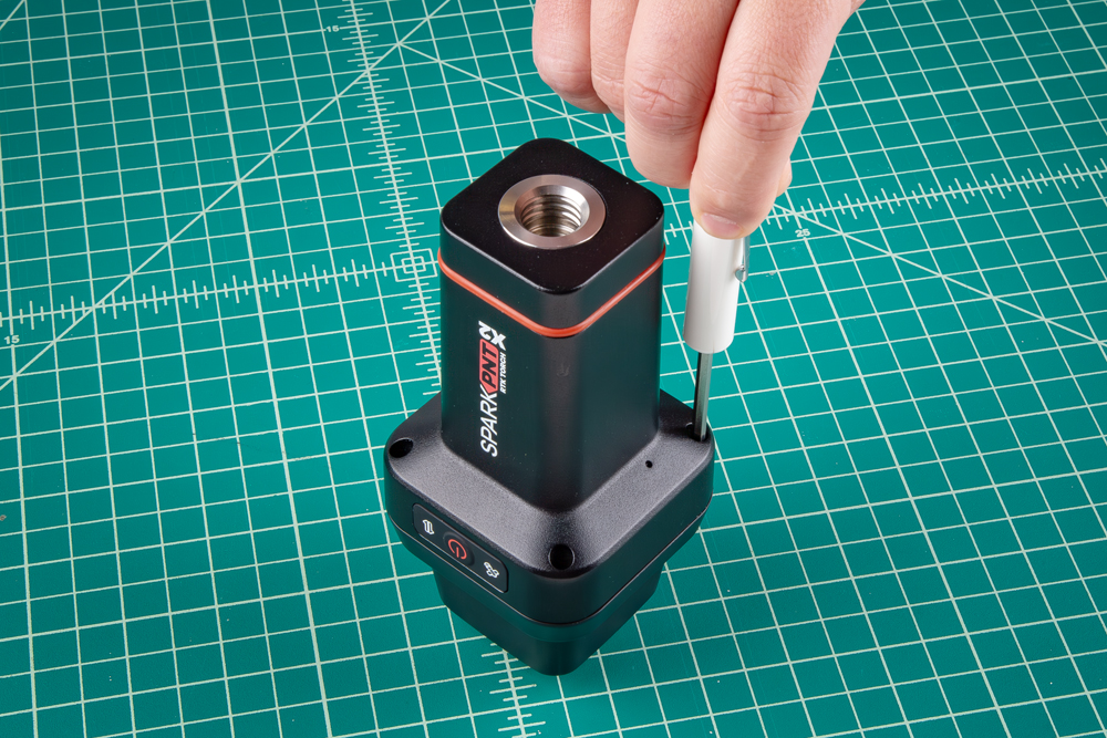
Be careful when threading these screws back into the cover. Over tightening or cross threading the screws into their holes, can strip out the screw head or eventually weaken the material fastening the screw.
Once unscrewed, the plastic cover should come right off, exposing the helical GNSS and WiFi/BLE antennas underneath.
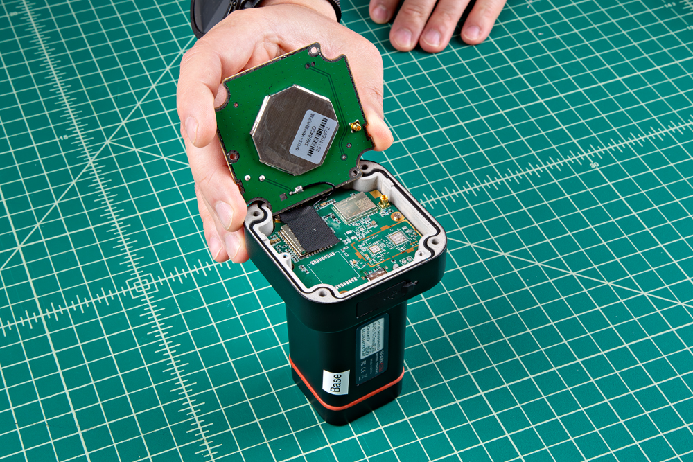
Remove the Antenna Stackup
Once the antenna cover is removed, users can access the three Phillips head screws holding the antenna in place.

One of the screws may be hiding under the QC sticker.
With the screws removed, gently and very carefully pop the upper PCB antenna off. There is an MMCX connector that will pop loose, along with a U.FL cable underneath. Pulling too hard may damage the connections, the PCB antennas, or both.
Do not pull on the film of the helical GNSS antenna. This will damage the antenna element and alter its tuning.
If you are having difficulties, it may help to gently and carefully pry up on the PCB, near the MMCX connector. The MMCX connector, is near the edge of the PCB and can be identified by its five soldered PTH pins.

Once the antenna board has been dislodged, users will need to disconnect the U.FL cable from the mainboard PCB. The U.FL connector is held in place with a piece of tape, which must be removed to access it. Carefully disconnect the U.FL cable, users may want to use a U.FL tool to avoid damaging the connector.
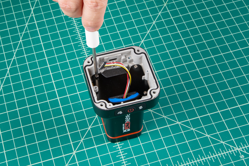
Remove the Mainboard PCB
Once the antenna stackup has been removed, users can access the three Phillips head screws holding the mainboard PCB in place.

Disconnect the battery connector from the bottom side of the mainboard PCB.
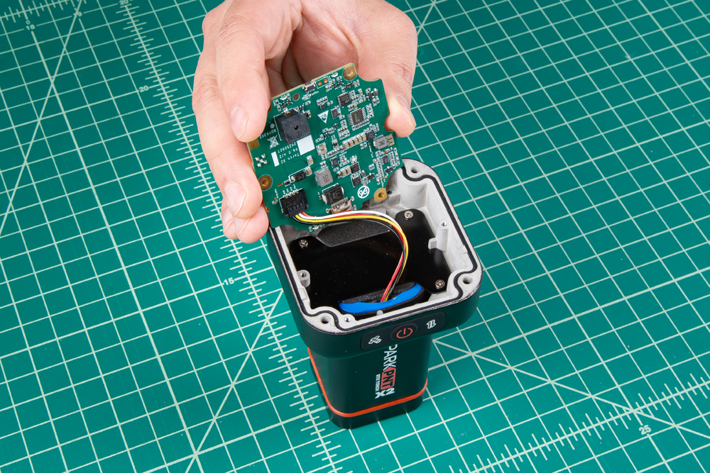
Remove the Battery Plate
Once the mainboard has been removed and the battery connector disconnected, the lower 7.2V LiPo battery pack is held in place with a metal retaining plate. Remove the Phillips head screws to replace the battery.