Surveying Setup
Setting up your hardware is simple.
Assembly
The TX2 has a standard 5/8" 11-TPI threaded base and is compatible with most surveying equipment. Users may elect to mount their mobile device (i.e. phone, laptop, or tablet) to the surveying equipment for ease of operation.

Orientation and Alignment
For the most accurate positioning, users should align their device as vertically straight as possible. Additionally, the user interface's power button (front of the device) should be facing north as defined by the device's north reference point.
When marking positions, users can also provide the pole height and distance between the ARP and APC in the RTK Everywhere firmware. This will allow users to accurately mark their positions based on the bottom of the surveying pole.
Placement and Surroundings
This section provides general placement considerations for precision GNSS surveying. Below, are some useful examples of ideal locations for surveying.
- Ideal locations
- Open fields
- Hilltops
- Poor locations
- Canyons and valleys
- Cities or dense urban areas
- Dense foilage
Obstructions and Multipath
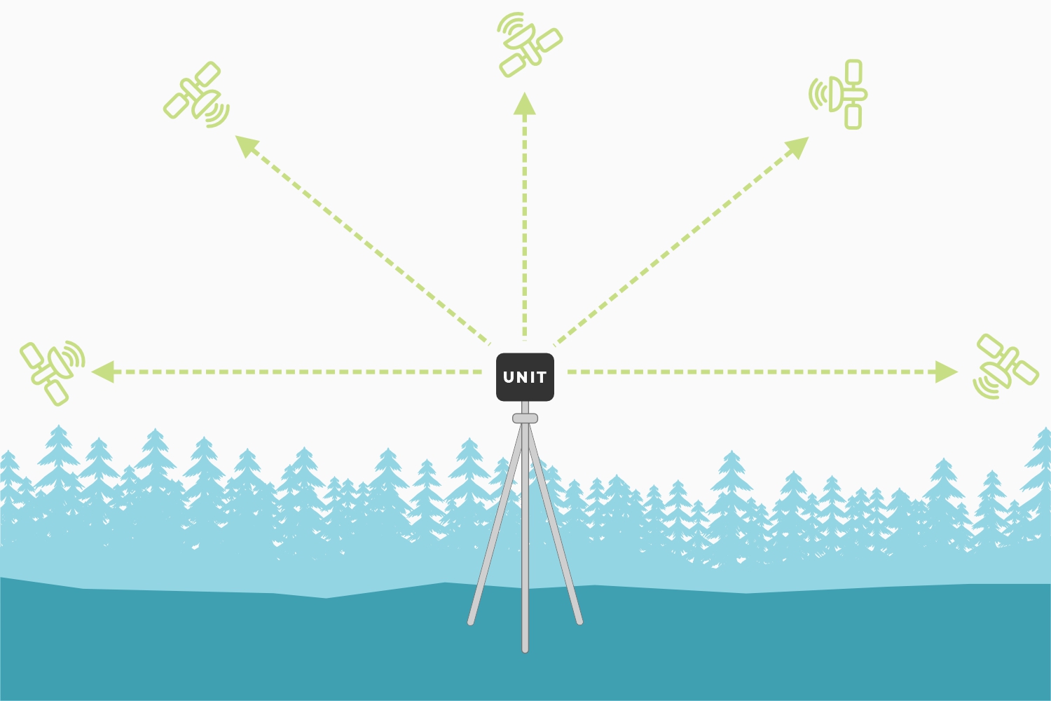
For precision GNSS surveying, the receiver works best with a wide-open, unobstructed view of the sky.
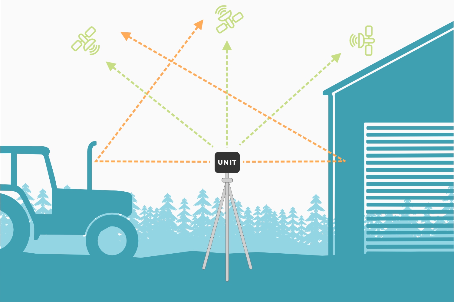
Obstructions can create multiple paths for signals. This introduces timing errors into the solutions provided by the GNSS receiver reducing its precision and accuracy.
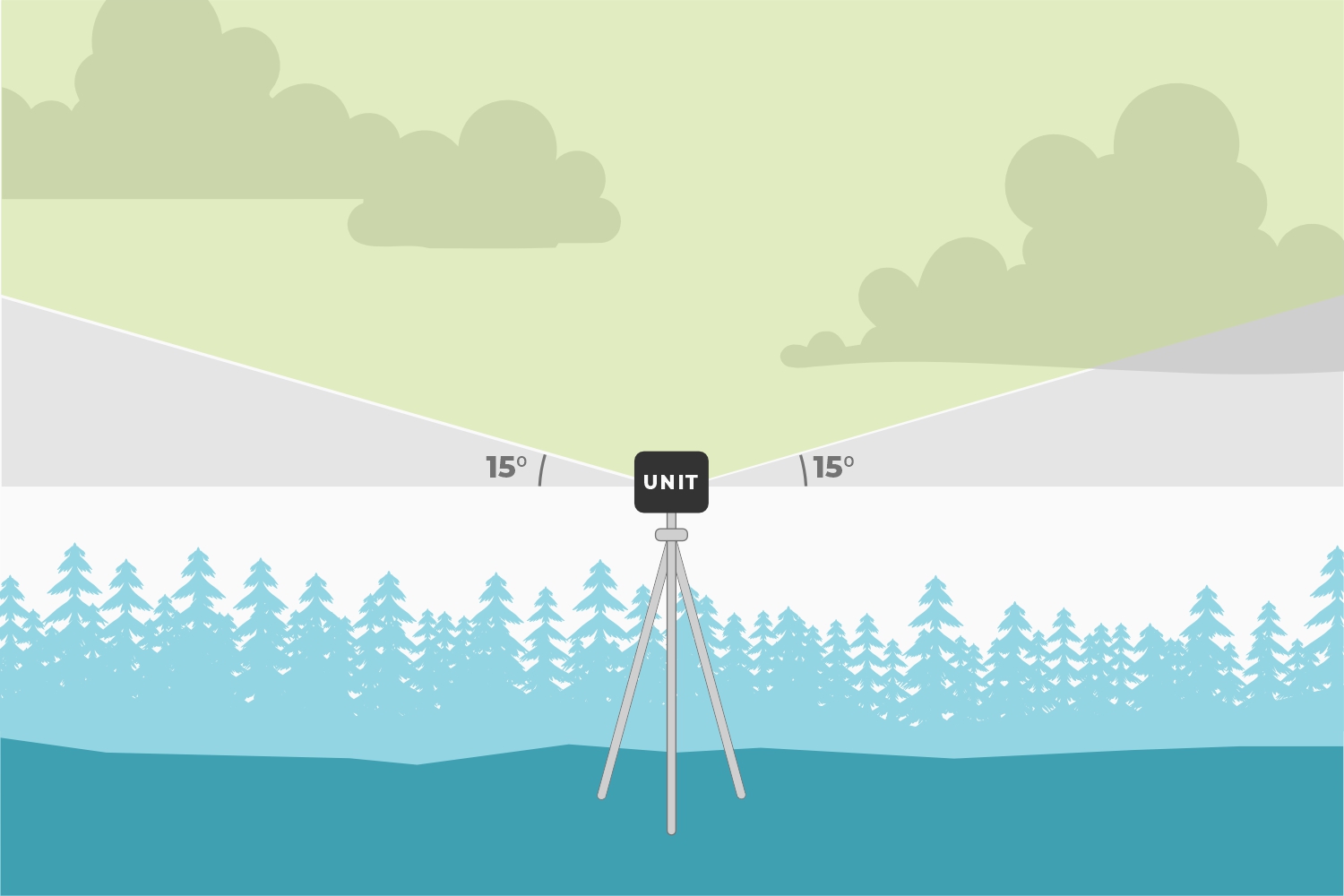
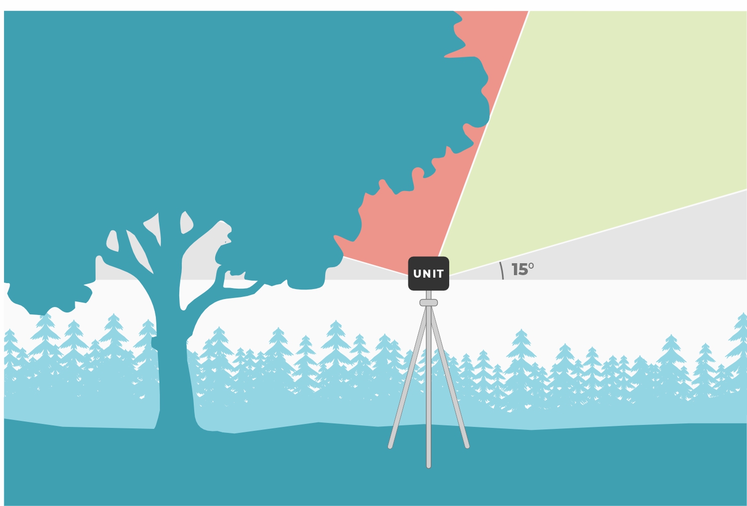
By default, the TX2 ignores any signals from satellites positioned below, 15° above its horizon (see image). This mitigates any multi-path errors from any obstacles on the horizon; such as buildings, trees, cars, etc.
Obstructions can also reduce the performance of the GNSS receiver and the precision of its solutions.
Dilution of Precision
The geometric arrangement of satellites, significantly influences the precision of GNSS solutions. A well-distributed arrangement of satellites allows for more accurate positioning by minimizing errors related to signal distortion and multipath effects. When satellites are positioned at wide angles relative to each other, the geometric dilution of precision improves, enhancing precision of the positioning solutions. Conversely, when satellites cluster closely together in the sky, it can lead to degradation in the geometric dilution of precision and less reliable positioning solutions. Therefore, optimal satellite geometry is crucial for achieving high-precision GNSS solutions.
RF Interference Sources
Nearby electronics can interfere with the reception of the GNSS signals. It is recommended that users limit the use of wireless electronics that produce RF noise. Especially those that operate near the frequencies of GNSS signal bands. This includes environments with high amounts of EMI, such as around TV broadcast stations or vehicles, radio masts, transmission towers, and overhead power lines.
